19. Proposed wiring diagrams
Legend for the proposed wiring diagrams on pages 19 and 20
(included in AUMA delivery)
18
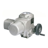
Part-turn actuators SG 03.3 – SG 04.3
AUMA NORM Operation instructions
S 3/ WSR Limit switch, closing, clockwise rotation
S 4/ LSO Limit switch, opening, counter-clockwise rotation
F 1/ TH Thermoswitch (motor protection)
R 1 / H Heater
R 2 / f1 Potentiometer
S 12 Local control switch OPEN – STOP – CLOSE
XA Customer connection at the AUMA plug/ socket connector
C
B
Capacitor (1 or 2 pieces)
 Loading...


