9. Electrical connection Work on the electrical system or equipment must only be
carried out by a skilled electrician himself or by specially
instructed personnel under the control and supervision of
such an electrician and in accordance with the applicable
electrical engineering rules.
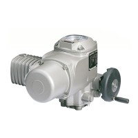
9.1 Connection with AUMA plug/ socket connector
.
Check whether type of current, supply voltage and frequency correspond
to motor data (refer to name plate at motor).
.
Loosen bolts (26.01) (figure C1) and remove plug cover (26.0).
.
Loosen screws (26.2.5) and remove socket carrier (26.2) from plug cover
(26.0).
.
Insert cable glands suitable for connecting cables.
.
Enclosure protection IP 67 or IP 68 is only ensured if
suitable cable glands are used.
.
Seal cable entries which are not used with suitable plugs.
.
Connect cables according to order related terminal plan KMS . . . . The ter
-
minal plan applicable to the actuator is attached to the handwheel in a
weather-proof bag, together with the operation instructions. In case the
wiring diagram is not available, it can be obtained from AUMA (state com
-
mission no., refer to name plate) or downloaded directly from the Internet
(see page 27).
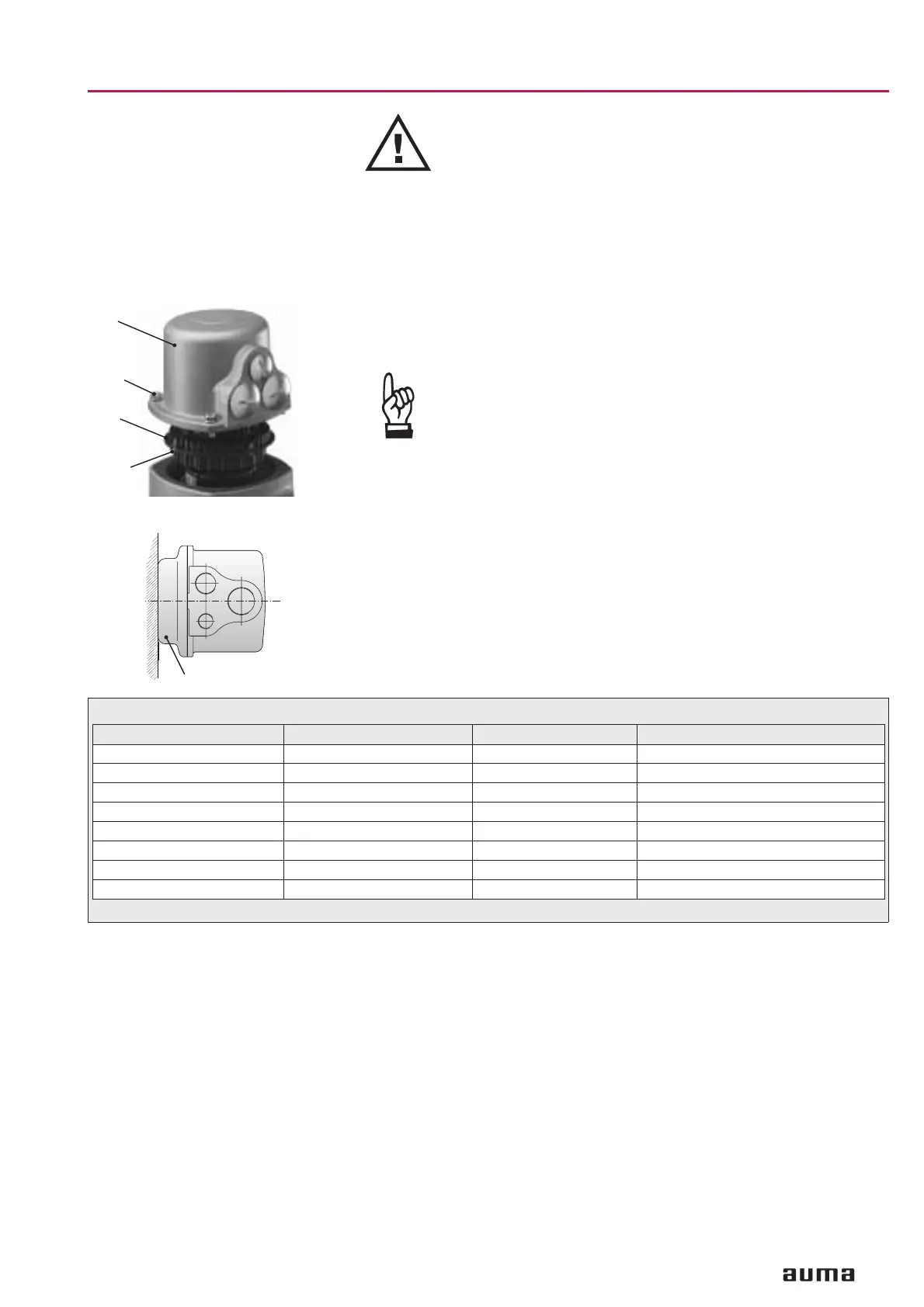
A special parking frame for protection against touching the bare contacts
and against environmental influences is available (see address list page 28).
9.2 Heater AUMA part-turn actuators have a heater installed as standard. To prevent
condensation, the heater must be connected. Refer to proposed wiring dia
-
grams on pages 19 and 20.
9.3 Motor protection In order to protect against overheating a thermoswitch is embedded in the
motor windings and has to be connected to the external control circuit. The
thermoswitch is tripped as soon as the max. permissible windings tempera
-
ture is reached. After the motor has cooled down to a temperature of approx.
90 °C, the actuator can be switched on again. Our warranty for the motor will
lapse if the thermoswitch is not connected.
9
Part-turn actuators SG 03.3 – SG 04.3
Operation instructions AUMA NORM
Figure C1: Connection
26.0
26.01
26.2
26.2.5
Figure C2: Parking frame (accessory)
Parking frame
Technical data Motor power connections
1)
Protective earth Control pins
No. of contacts max. 6 (3 are used) 1 (leading contact) 50 pins / sockets
Marking U1, V1, W1, U2, V2, W2 according to VDE 1 to 50
Voltage max. 750 V – 250 V
Current max. 25 A – 16 A
Type of customer connection Screws Screw for ring lug Screws
Cross section max. 6 mm
2
6 mm
2
2.5 mm
2
Material:Pin / socket carrier Polyamide Polyamide Polyamide
Contacts Brass (Ms) Brass (Ms) Brass, tin plated or gold plated (option)
1) Suitable for copper wires. For aluminium wires contact AUMA.
Table 3: Technical data AUMA plug/ socket connector
 Loading...


