10.2 Setting for end position OPEN (white section)
.
Turn handwheel counter-clockwise until valve is open.
.
Turn handwheel approx. 1 turn in direction CLOSE and then half a turn in
direction OPEN.
.
Press down and turn setting spindle D (figure E) with screw driver (5 mm)
in direction of arrow, thereby observe switch cam E. While a ratchet is felt
and heard, the switch cam E moves 90° every time. When switch cam E is
90° from the switch, continue turning slowly.
When the switch cam E snaps and trips the switch, stop turning and
release setting spindle.
If you override the tripping point inadvertedly (ratchet is heard after the
switch cam has snapped), continue turning the setting spindle in the same
direction and repeat the setting process.
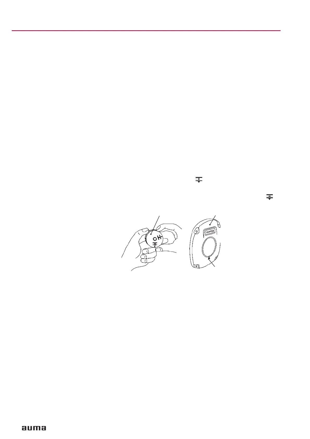
11. Setting of mechanical position indicator
Indicator disc rotates approximately 90° at full travel from OPEN to CLO
-
SED or vice versa.
.
Place indicator disc (figure F) on shaft.
.
Move valve to end position CLOSED.
.
Turn lower indicator disc until symbol CLOSED is in alignment with the
mark on the cover (figure L).
.
Move actuator to end position OPEN.
.
Hold lower indicator disc in position and turn upper disc with symbol
OPEN until it is in alignment with the mark on the cover.
12. Test run Check limit switching:
.
Move actuator manually (refer to page 5, clause 6.2) into both end posi
-
tions of the valve.
.
Check whether limit switching is set correctly. Hereby observe that the
appropriate switch is tripped in each end position and released again after
the direction of rotation is changed. If this is not the case, the limit swit
-
ching must first be set, as described from page 11.
If no optional components (clauses 13. to 15.) require setting:
.
Clean sealing faces at cover and housing; check whether O-ring is in good
condition. Apply a thin film of non-acidic grease to the sealing faces.
.
Replace cover on switch compartment and fasten bolts evenly crosswise.
12
Part-turn actuators SG 03.3 – SG 04.3
AUMA NORM Operation instructions
Figure F
Indicator disc
Cover
Mark
 Loading...


