2
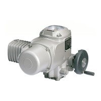
Part-turn actuators SG 03.3 – SG 04.3
AUMA NORM Operation instructions
Scope of these instructions:
These instructions apply to part-turn actuators of the type range
SG 03.3 – SG 04.3.
These operation instructions are only valid for ”clockwise closing”, i.e.
driven shaft turns clockwise to the valve.
Table of contents Page
1. Safety instructions 3
1.1 Range of application 3
1.2 Commissioning (electrical connection) 3
1.3 Maintenance 3
1.4 Warnings and notes 3
1.5 Further notes 3
2. Short description 3
3. Technical data 4
4. Transport and storage 5
5. Packaging 5
6. Fitting the ball handle/ manual operation 5
6.1 Fitting the ball handle 5
6.2 Manual operation 5
7. Mounting to valve 6
8. Checking the end stops 7
8.1 Setting of end stop CLOSED 7
8.2 Setting of end stop OPEN 8
8.3 Setting values for mechanical end stops 8
9. Electrical connection 9
9.1 Connection with AUMA plug/ socket connector 9
9.2 Heater 9
9.3 Motor protection 9
9.4 Remote position transmitter 10
9.5 Limit switch 10
9.6 Fitting of the cover 10
10. Setting the limit switching 11
10.1 Setting for end position CLOSED (black section) 11
10.2 Setting for end position OPEN (white section) 12
11. Setting of mechanical position indicator 12
12. Test run 12
13. Setting of the potentiometer (option) 13
14. Setting of electronic position transmitter RWG (option) 13
14.1 Setting of 2-wire system 4 – 20 mA and 4-wire system 0 – 20 mA 14
14.2 Setting of 4-wire system 4 – 20 mA 15
15. Setting of the electronic intermediate position detection (option) 16
16. Maintenance 17
17. Disposal and recycling 17
18. Service 17
19. Proposed wiring diagrams 18
19.1 Wiring diagram for SG with 1-phase AC motors 19
19.2 Wiring diagram for SG with 1-phase AC motors with reversing contactor controls 20
19.3 Wiring diagram for SG with 3-phase AC motors 21
20. Spare parts list part-turn actuator SG 03.3 – SG 04.3 22
21. Declaration of Conformity and Declaration of Incorporation 26
Index 27
Adresses AUMA offices and representatives 28