13. Setting of the potentiometer (option)
– For remote indication –
.
Move valve to end position CLOSED.
.
Take off cover at switch compartment.
.
Pull off indicator disc.
.
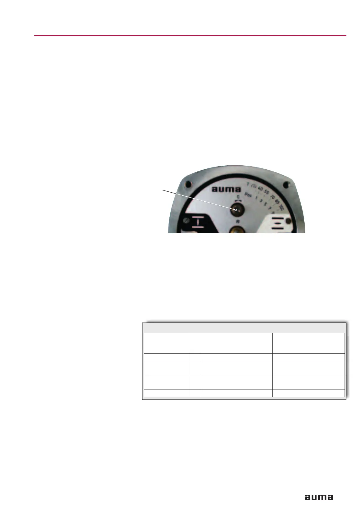
Turn potentiometer (R) counter-clockwise until stop is felt. End position
CLOSED corresponds to 0 %, end position OPEN to 100 %.
.
Turn potentiometer (R) slightly back from the stop.
.
Perform fine-tuning of the zero point at external setting potentiometer (for
remote indication).
.
Press indicator disc on shaft and perform setting as described on page
12, clause 9.
.
Clean sealing faces at cover and housing; check whether O-ring is in good
condition. Apply a thin film of non-acidic grease to the sealing faces.
.
Fit and fasten switch compartment cover.
14. Setting of electronic position transmitter RWG (option)
– For remote indication or external control –
After mounting the part-turn actuator to the valve, check setting by measu-
ring the output current (see subclause 14.1 or 14.2) and re-adjust, if neces
-
sary.
13
Part-turn actuators SG 03.3 – SG 04.3
Operation instructions AUMA NORM
Figure H
R
Terminal plans KMS _ _ _ _ R _ /_ _
4-wire system
KMS _ _ _ _ Z _ /_ _
KMS _ _ _ _ Z _ /_ _
2-wire system
Output current I
a
0 – 20 mA, 4 – 20 mA 4 – 20 mA
Supply voltage U
v
24 V DC, ±15 %
smoothed
12 V DC + (I x R
B
),
max. 30 V
Max. input current I 25 mA at 20 mA
output current
20 mA
Max. load R
B
600 Ω (Uv – 12 V) / 20 mA
Table 5: Technical data RWG 6020
 Loading...


