15. Setting of the electronic intermediate position detection (option)
Any application can be switched on or off via the two intermediate position
switches WDR/LSA and WDL/LSB.
The intermediate position detection is set in the factory according to order
details. If the customer requirements have not been mentioned in the order,
the intermediate positions have been set to 5 mA (WDR/LSA) and 15 mA
(WDL/LSB)
In case other intermediate positions are required they have to be set as fol
-
lows:
.
Connect voltage for electronic position transmitter.
.
Take off cover at switch compartment.
.
Move valve to end position CLOSED.
.
Connect ammeter for 0 – 20 mA to measuring points (MP1/ MP2).
(Measured value for normal operation = 0 mA or 4 mA, for inverse opera
-
tion = 20 mA)
.
Turn trimmer potentiometer (R9) clockwise, until the yellow LED V9 is no
longer illuminated.
.
Move valve in direction OPEN. Stop the actuator when reaching the desi
-
red intermediate position (WDR/LSA).
.
Turn trimmer potentiometer (R9) counter-clockwise, until the yellow LED
V9 is illuminated. The intermediate position WDR/LSA is now set.
.
Move valve to end position OPEN. (Measured value for normal operation
= 20 mA, for inverse operation = 0 mA or 4 mA)
.
Turn trimmer potentiometer (R10) counter-clockwise, until the green LED
V10 is no longer illuminated.
.
Move valve in direction CLOSE. Stop the actuator after reaching the desi
-
red intermediate position (WDL/LSB).
.
Turn trimmer potentiometer (R10) clockwise, until the green LED V10 is
illuminated. The intermediate position WDR/LSB is now set.
.
Clean sealing faces at cover and housing; check whether O-ring is in good
condition. Apply a thin film of non-acidic grease to the sealing faces.
.
Replace cover on switch compartment and fasten bolts evenly crosswise.
16
Part-turn actuators SG 03.3 – SG 04.3
AUMA NORM Operation instructions
MOV
M
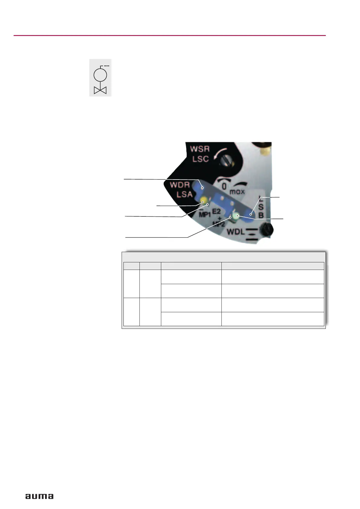
Figure K
R6 “0”
MP1 (–)
MP2 (+)
R10
V10 (green) =
WDL/ LSB
reached
M9 (yellow) = WDR/ LSA reached
No Colour Function Description
V9 yellow is illuminated:
WDR/LSA reached
The current, and consequently, the positi-
on have reached the set value
is not illuminated:
no WDR/LSA
The intermediate position WDR/LSA has
not yet been reached
V10 green is illuminated:
WDL/LSB reached
The current, and consequently, the positi
-
on have reached the set value
is not illuminated:
no WDR/LSB
the intermediate position WDL/LSB has
not yet been reached
Table 6
 Loading...


