8. Checking the end stops
This check can only be performed on valves which are not yet mounted into
a pipeline.
8.1 Setting of end stop CLOSED
.
Check whether mechanical end position of the valve corresponds to the
mechanical end stop of actuator by turning at handwheel (clockwise for
end position CLOSED)
.
If necessary, remove screw plug (22.1, figure B1) and adjust mechanical
end stop at hex. socket head cap screw (21.1, figure B3). Turning clock
-
wise results in smaller, turning counter-clockwise results in larger swing
angles.
.
Never remove the screws (21.2, figure B2 and 21.1, figure
B3) completely, because this will cause oil leakage.
.
Observe dimension T
min.
(subclause 8.3).
.
Check O-ring in screw plug and replace if damaged.
.
Replace and fasten screw plug (22.1, figure B1).
7
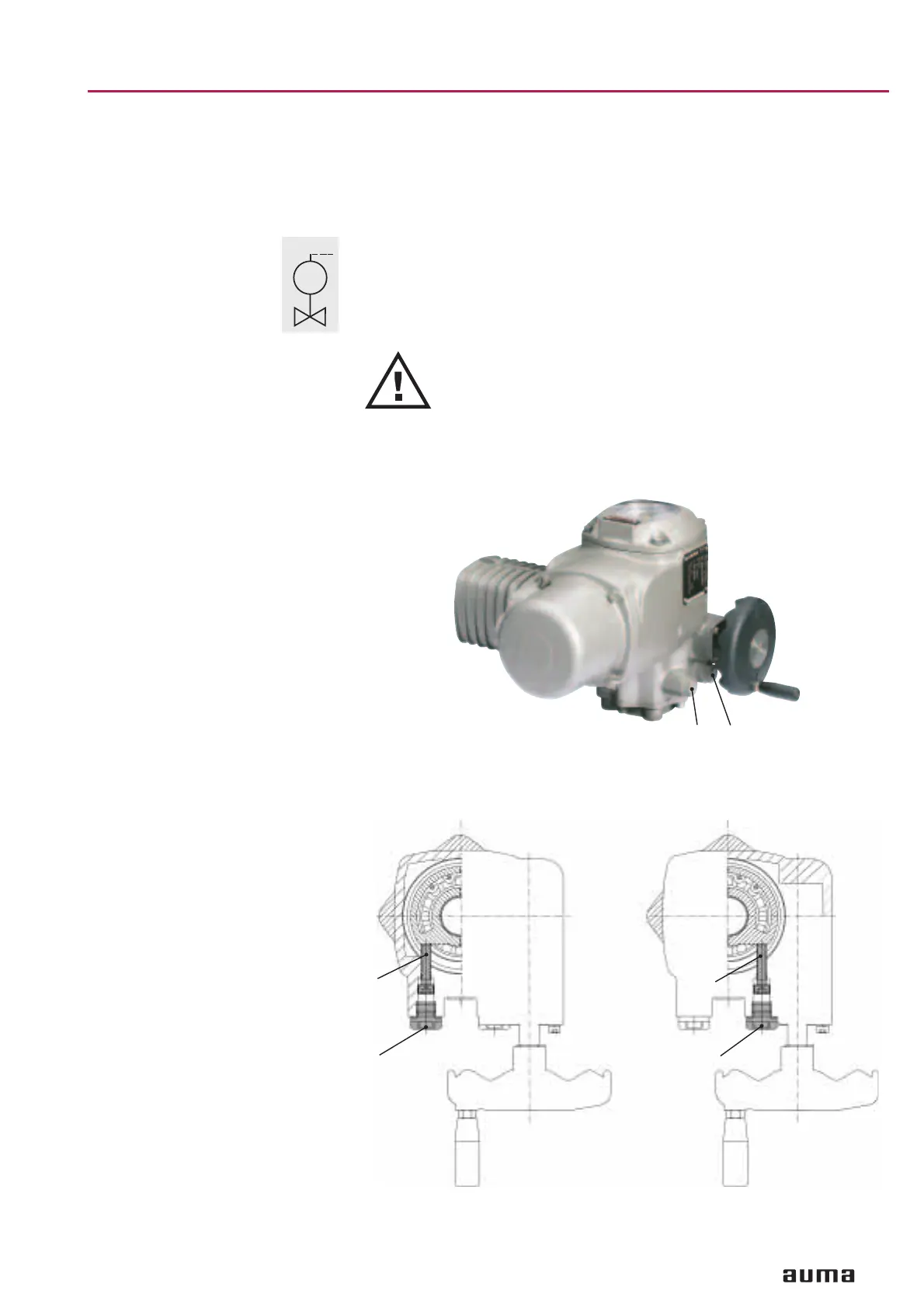
Part-turn actuators SG 03.3 – SG 04.3
Operation instructions AUMA NORM
MOV
M
Figure B1
22.2
22.1
Fig. B2: Setting end position OPEN Fig. B3: Setting end position CLOSED
(view from top) (view from top)
21.2
22.2 22.1
21.1