23
Part-turn actuators SG 03.3 – SG 04.3
Operation instructions AUMA NORM
Note:
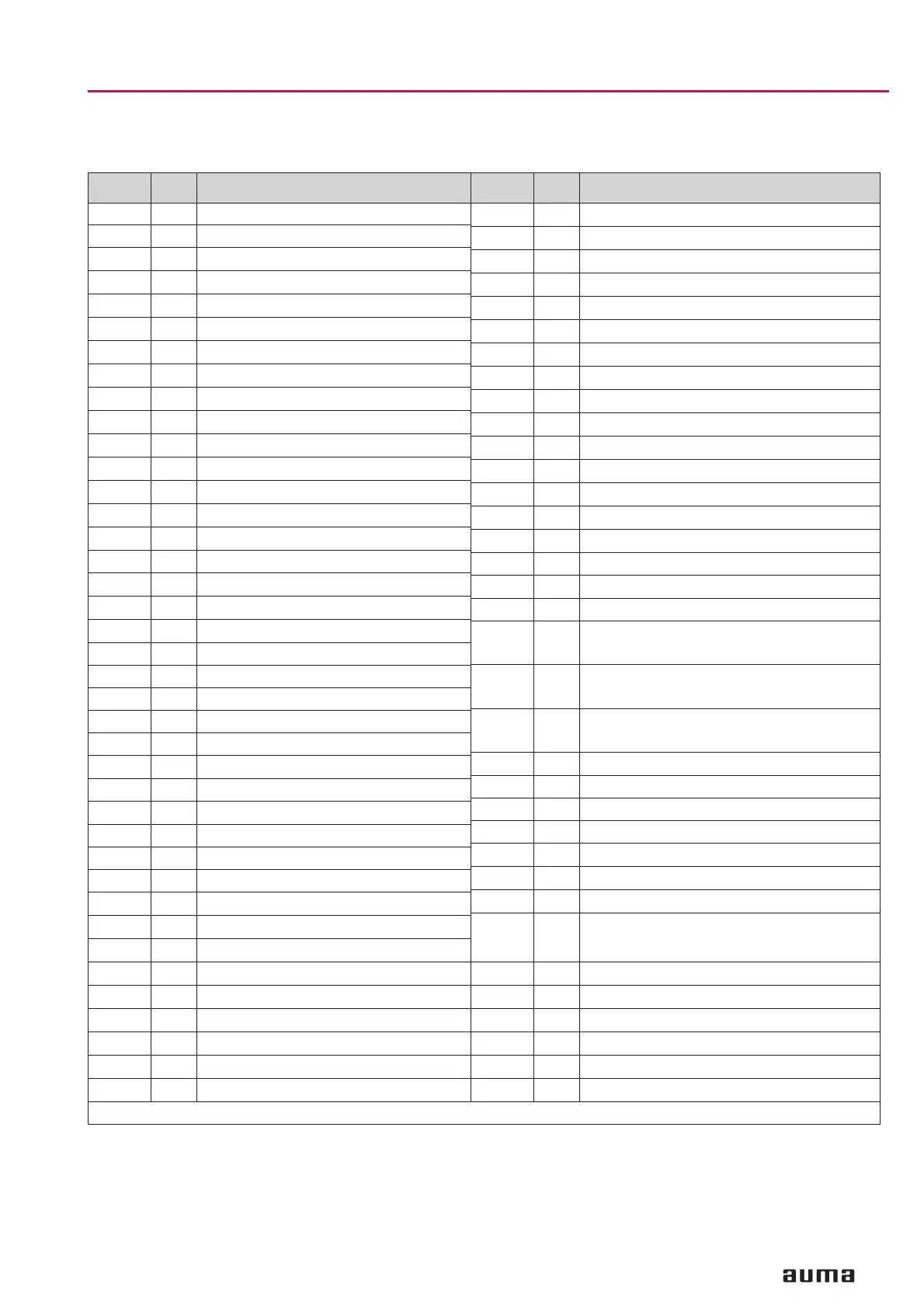
When placing your order for spare parts , please mention type of part-turn actuator and our commission number
(refer to name plate).
1) optional extra, not included in basic equipment
No. Type Designation
01 E Capacitor
02 E Capacitor
03
E
Spring dowel
04
E
Retaining washer
05
E
Circlip
06
E
Retaining washer
08
E
Screw
09
E
Lock washer
010
E
Verbus-Tensilock screw
011
E
Countersunk screw
012
E
Bearing bush
018
E
Circlip
1.0
B
Housing
2.0
B
Mounting flange assly.
3.0
B
Drive wheel assly.
3.01 E Ball bearing
3.02
E
Circlip
3.04
E
Circlip
4.0
B
Worm shaft assly.
4.01 E Ball bearing
4.02 E Circlip
4.1 E Worm shaft
5.0 B Worm wheel shaft assly.
5.01 E Ball bearing
5.02
E
Ball bearing
5.1 E Worm wheel shaft
6.0
B
Worm wheel assly.
8.0 B Ellipto-centric gearing assly.
8.01 E Dowel pin
8.7 E Coupling disc
8.8
B
Ellipto-centric gearing
9.0
B
Motor pinion assly.
10.0
B
Spur gear assly.
11
E
Cable protection
12.0
B
Worm shaft manual drive assly.
13.0
B
Retaining flange assly.
14.0
B
Handwheel assly.
15
E
Cover disc
16.0
B
Hex. socket head cap screw - limit stop assly.
Type B = Sub-assembly Type E = Component
No. Type Designation
17
E
Screw plug
17. 0
B
Screw plug assly.
18
E
Bearing bush
19
E
Bearing bush
20
E
Coupling
21
E
Spigot ring
23.0
B
Control unit assly.
23.2
B
Heater
23.3
B
Switch
23.5
B
Mechanical position indicator
23.6
B
Blinker transmitter
23.10
E
Cover plate
24
B
Wire for protective earth
25
B
Pin carrier assly. (without pins)
25.2.2
B
Pin for motor
25.2.3 B Pin for control
26.0
B
Plug cover assly.
26.2 B Socket carrier assly. (complete with sockets)
26.2.2
B
Socket for motor
(included in sub-assembly 26.2 )
26.2.3
B
Socket for control
(included in sub-assembly 26.2)
26.2.4
B
Socket for protective earth
(included in sub-assembly 26.2)
27.0
B
Cover assly.
30.0 B Motor assly.
152.0 B Potentiometer assly.
1)
152.1 E Potentiometer
1)
152.2
E
Slip clutch for potentiometer
1)
152.4
E
Pinion for potentiometer
1)
153.0
B
Electronic position transmitter RWG 6020
1)
153.1 E
Potentiometer for RWG 6020
(without slip clutch)
1)
153.2
E
Slip clutch for RWG 6020
1)
153.3
E
Electronic board RWG 6020
1)
153.4
E
Pinion for RWG 6020
1)
S1
S
Set of seals, small
S2
S
Set of seals, large
Type S = Set assly. = assembly
 Loading...


