2. Insert cable gland suitable for connecting cable.
➥
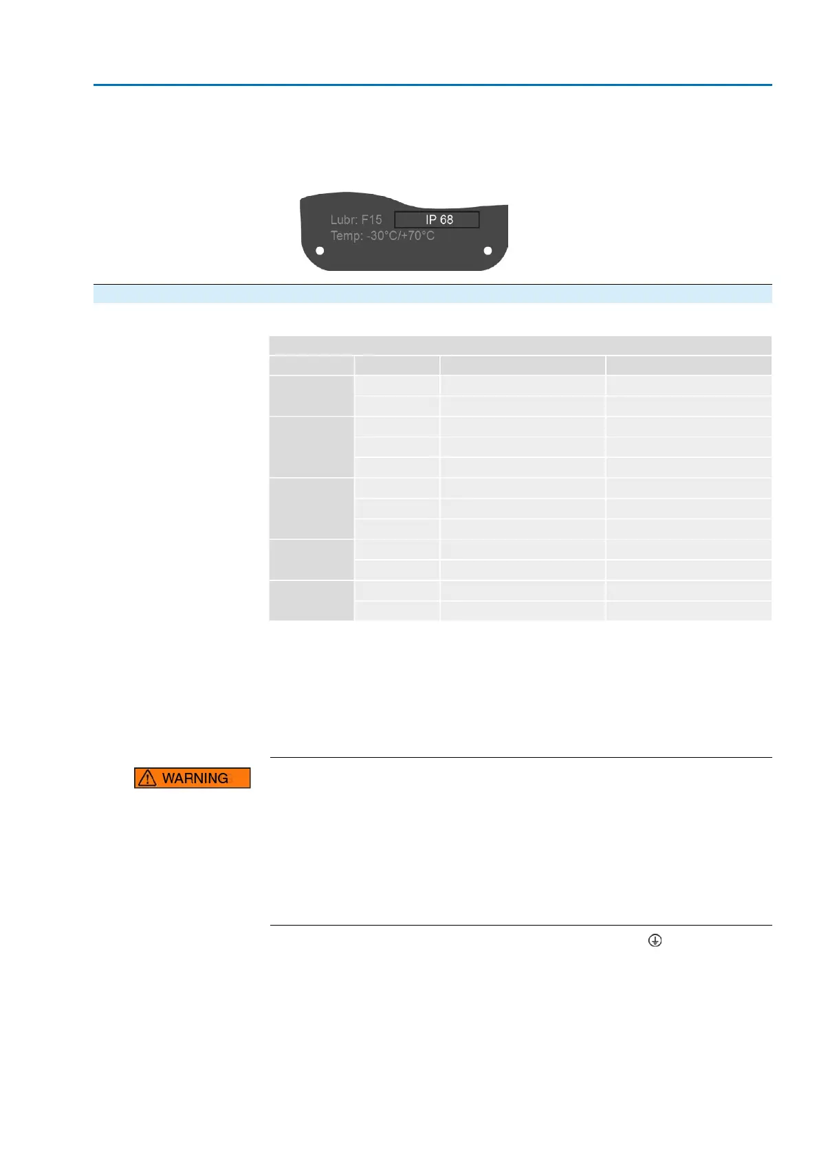
The enclosure protection IP… stated on the name plate is only ensured if suit-
able cable glands are used.
Figure 34: Name plate, example with enclosure protection IP68
5.3.1.2. Motor cables: connect
Table 22:
Terminal cross sections and terminal tightening torques
Tightening torquesTerminal cross sectionsSpeedType
2.0 Nm0.5 – 16 mm
2
4 – 22SA 25.1
SAR 25.1
3.5 Nm2.5 – 35 mm
2
32 – 90
1.2 – 2.4 Nm4 – 16 mm
2
4 – 22SA 30.1
SAR 30.1
4.0 – 5.0 Nm10 – 35 mm
2
32 – 45
6.0 – 12 Nm16 – 70 mm
2
63 – 90
1.2 – 2.4 Nm4 – 16 mm
2
4 – 5.6SA 35.1
4.0 – 5.0 Nm10 – 35 mm
2
8 – 22
6.0 – 12 Nm16 – 70 mm
2
32 – 45
4.0 – 5.0 Nm10 – 35 mm
2
4 – 11SA 40.1
6.0 – 12 Nm16 – 70 mm
2
16 – 32
4.0 – 5.0 Nm10 – 35 mm
2
4SA 48.1
6.0 – 12 Nm16 – 70 mm
2
5.6 – 16
1. Remove cable sheathing and insert the wires into the cable glands.
2. Fasten cable gland with the specified torque to ensure required enclosure pro-
tection.
3. Strip wires.
4. For flexible cables: Use end sleeves according to DIN 46228.
5. Connect cables according to order-related wiring diagram.
In case of a fault: Hazardous voltage while protective earth conductor is NOT
connected!
Risk of electric shock.
→
Connect all protective earth conductors.
→
Connect PE connection to external protective earth conductor of connecting
cables.
→
Start running the device only after having connected the protective earth con-
ductor.
6.
Firmly tighten protective earth to PE connection (symbol: ).
7. For shielded cables: Link the cable shield end via the cable gland to the housing
(earthing).
37
SA 25.1 – SA 48.1/SAR 25.1 – SAR 30.1
AC 01.2 Intrusive HART Electrical connection