11.3.2.2. Test/replace fuses F3/F4
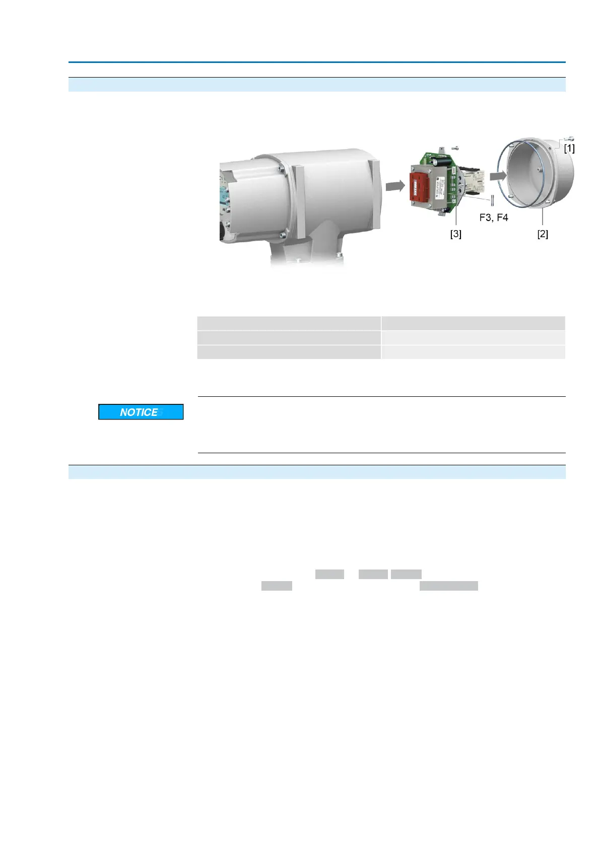
1. Loosen screws [1] and remove cover [2] on the rear of the actuator controls.
Figure 88:
Check fuses.
2. The power supply unit has measurement points (solder pins) allowing to perform
a resistance (continuity) measurement:
Table 40:
Measuring pointsChecking
MTP5 – MTP6F3
MTP7 – MTP8F4
3. To replace defective fuses: Carefully loosen power supply unit [3] and pull out.
(The fuses are on the equipped part of the power supply board.)
Cable damage due to pinching!
Risk of functional failures.
→
Carefully assemble power supply unit to avoid pinching the cables.
11.3.3. Motor protection (thermal monitoring)
In order to protect against overheating and impermissibly high surface temperatures
at the actuator, PTC thermistors or thermoswitches are embedded in the motor
winding. Motor protection trips as soon as the max. permissible winding temperature
has been reached.
The actuator is switched off and the following signals are given:
●
LED 3 (motor protection trippped) on the local controls is illuminated.
●
The status indication S0007 or S0011 Failuredisplays a fault..
The fault Details is displayed when selecting Thermal fault.
The motor has to cool down before operation can be resumed.
Depending on the parameter setting (motor protection behaviour), the fault signal is
either automatically reset or the the fault signal has to be reset using RESET push
button with selector switch position Local operation (LOCAL).
85
SA 25.1 – SA 48.1/SAR 25.1 – SAR 30.1
AC 01.2 Intrusive HART Corrective action