15. Test run
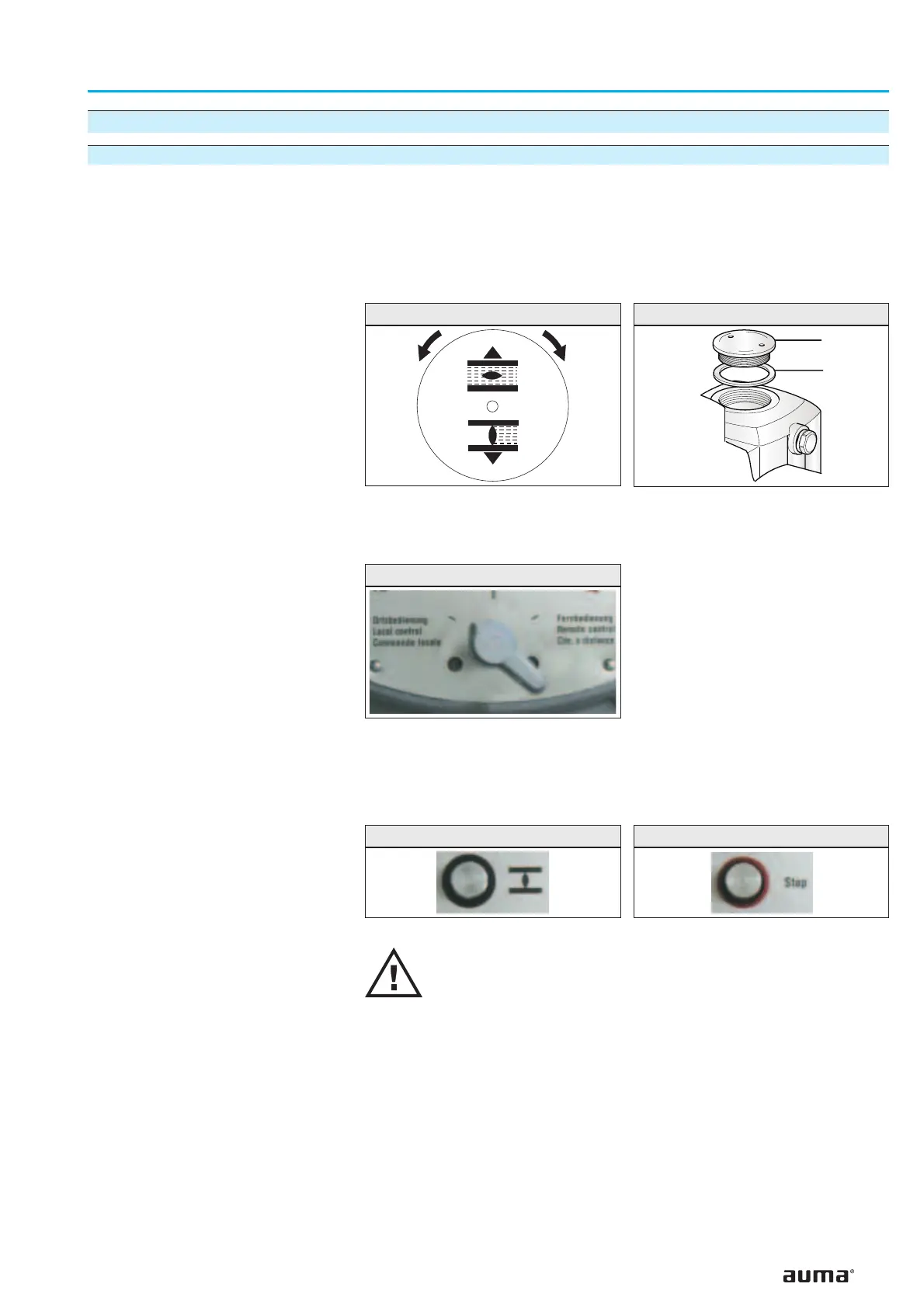
15.1 Checking the direction of rotation
.
If provided, place indicator disc on shaft.
The direction of rotation of the indicator disc (figure 29) indicates the
direction of rotation of the output drive.
.
If there is no indicator disc, the direction of rotation can also be observed
on the hollow shaft. For this purpose, remove screw plug (no. 27)
(figure 30).
.
Move actuator manually to intermediate position or to sufficient distance
from end position.
.
Set selector switch to local control (I) (figure 31).
.
Switch on the voltage supply.
.
Press push button CLOSE (figure 32) and observe the direction
of rotation:
If the indicator disc turns counterclockwise, the direction of rotation
is correct.
If the direction of rotation is wrong, switch off immediately.
Afterw
ards, correct phase sequence in the connecting cable from
the wall bracket to the actuator and repeat test run.
25
Multi-turn actuators SA 07.1 – SA 30.1/SAR 07.1 – SAR 30.1
Operation instructions with actuator controls AUMA MATIC AM 01.1/AM 02.1
Figure 29: Indicator disc
CLOSED
OPEN
Figure 30: Opening the hollow shaft
27
S1/S2
Figure 31: Selector switch LOCAL
Figure 32: Push button CLOSE Figure 33: Push button STOP
 Loading...

