21.6 Positioner adjustment for end position OPEN (inverse operation)
In standard version the maximum input signal (E1 = 20 mA) results in opera
-
tion to end position OPEN.
.
By switching the code switch S3-7 (figure 52) to position “1”, an inversion
of this signal definition (inverse operation) can be achieved.
.
In case an RWG (option) is installed, the connections 7 (red) and 5 (black)
on the positioner board (figure 38) of the actuator have to be exchanged.
.
In case a potentiometer is installed, (option) the connections 21 (red) and
22 (black) at XA (connection for actuator) must be interchanged.
Before beginning the setting of the positioner, it has to be
ensured that the limit and tor
que switching of the actuator
as well as the feedback have been set (clauses 16. and 17.).
.
Set selector switch (local controls) to position LOCAL.
.
Run actuator with push button to end position OPEN .
.
Supply nominal value E1 of 0 or 4 mA (see wiring diagram).
.
Turn potentiometer “t-off” (P10) counterclockwise to the stop
(figure 52).
Missing signals E1/E2 or wrong polarity are indicated by
LED (V10) “E1/E2 < 4 mA" (figures
50 or 52)
.
Connect voltmeter to measuring points MP3 and MP4 (figure 52) for mea-
suring the nominal value (0 – 5 V).
For a nominal value E1 of 0 mA, the voltmeter shows 0 V.
For a nominal value E1 of 4 mA, the voltmeter shows 1 V.
In case nominal value (0 V or 1 V) is not correct:
Correct nominal value signal in control room.
.
Connect voltmeter to measuring points MP2 and MP1 for measuring the
actual value signal.
For an actual value E2 of 0 mA, the voltmeter shows 0 V.
For an actual value E2 of 4 mA, the voltmeter shows 1 V.
Adjust position feedback according to clause 16. and 17. and repeat
“positioner adjustment”.
41
Multi-turn actuators SA 07.1 – SA 30.1/SAR 07.1 – SAR 30.1
Operation instructions with actuator controls AUMA MATIC AM 01.1/AM 02.1
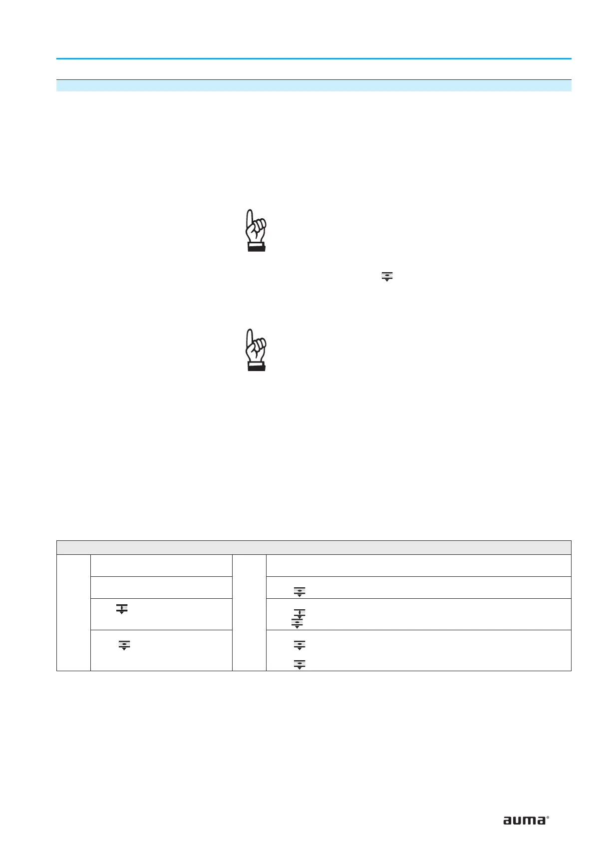
If
Possible LED display:
(refer to figures 50 and 52)
Then
Required setting in end position OPEN:
(refer to figures 50 and 52)
the LEDs are not illuminated
Turn potentiometer “0” (P3) slightly clockwise until
LED (V28 green) is illuminated
LED (V27 yellow)
is illuminated
Turn potentiometer “0” (P3) slightly clockwise until
LED (V27 yellow) is no longer illuminated and
LED (V28 green) is illuminated
LED (V28 green)
is illuminated
Turn potentiometer “0” (P3) counterclockwise until
LED (V28 green) is no longer illuminated.
Then turn potentiometer “0” (P3) slightly clockwise until
LED (V27 yellow) is illuminated
Table 10
 Loading...

