●
SIL failure (signal active), i.e.:
NO (NO contact) output = open
NC (NC contact) output = closed
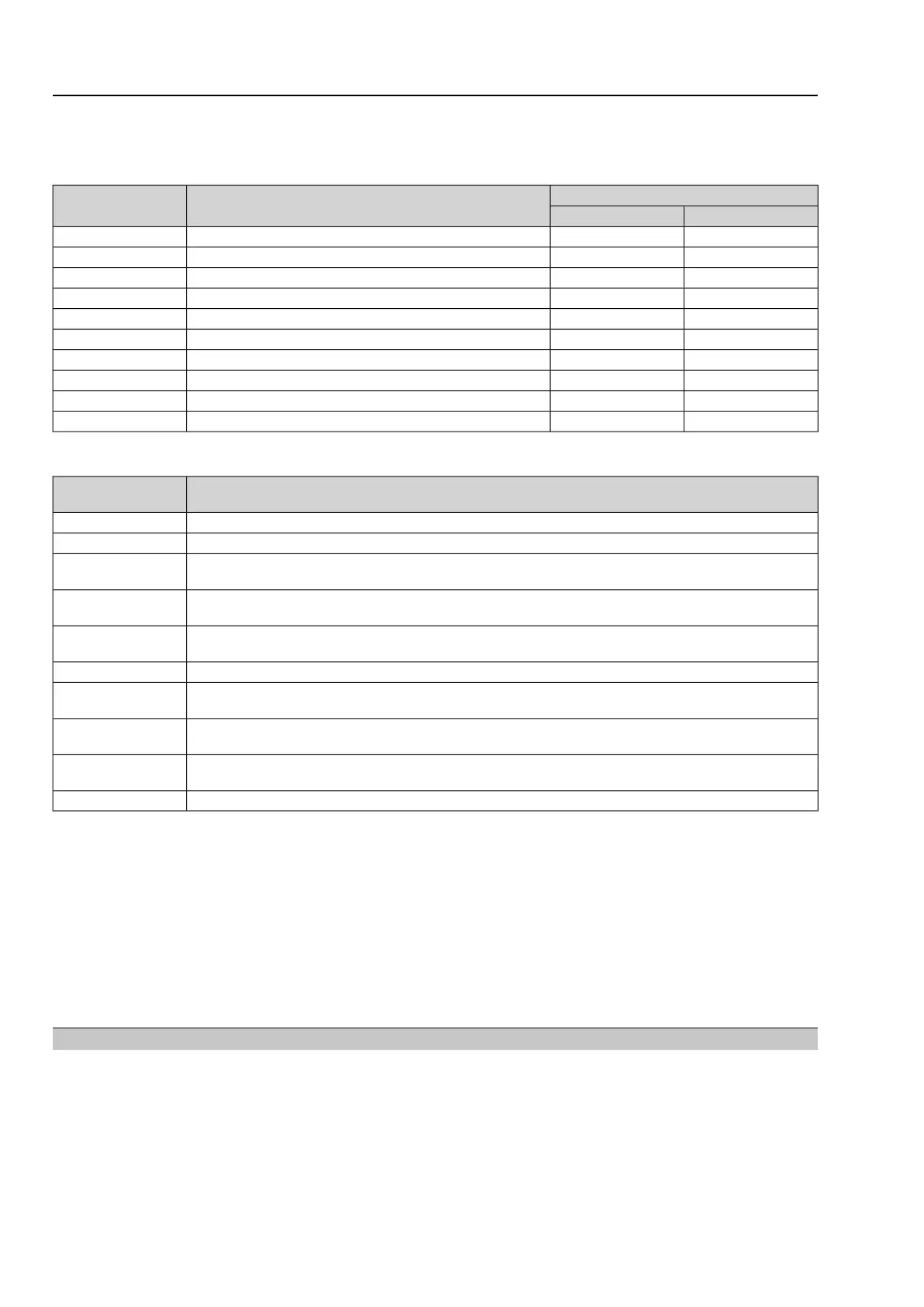
Customer connections for controlSignalDesignation
Wiring diagram
[2] Fieldbus[1] Parallel
XK 3XK 31Digital input for Safe ESD functionSafe ESDa
XK 5XK 32Redundant input for Safe ESD functionSafe ESDb
XK 7XK 33Reference potential for Safe ESDa and Safe ESDb0 V
XK 8XK 35Digital input for Safe STOP function in direction CLOSESafe STOP CLOSE
XK 9XK 37Reference potential for Safe STOP CLOSE0 V
XK 10XK 36Digital input for Safe STOP function in direction OPENSafe STOP OPEN
XK 11XK 38Reference potential for Safe STOP OPEN0 V
XK 15XK 40NO contact of SIL fault signalSIL ready
XK 14XK 39NC contact of SIL fault signalSIL failure
XK 16XK 42Reference potential for SIL fault signalCom.
SIL fault displayed via SIL failure output
DescriptionFault causes
SIL
Motor protection trippedThermal fault
Torque fault in directions OPEN and/or CLOSETorque fault
Current position feedback is outside permissible range.Fault position feed-
back
One phase of power supply is missing.
Controls are not supplied with mains voltage
Phase failure
The phase conductors L1, L2 and L3 are connected in the wrong sequence.Phase sequence
fault
The safety-related part of controls is without power supply.Power supply failure
Temperature within controls housing too high
Failure of heating system for ambient temperatures below –25 °C
Temperature fault
Actuator of valve lockedFailure of actuator
monitoring
Both signals Safe ESDa and Safe ESDb are not simultaneously on the same level.Fault in redundant
wiring Safe ESD
Internal error of the SIL moduleInternal error
For further information on SIL faults and in particular to assist in troubleshooting,
refer to chapter <Indications>.
Information The basic function "automatic correction of direction of rotation" is not available for
this version.When connecting the power supply ensure that phases L1, L2 and L3
are correctly connected. For checking the direction of rotation, refer to operation in-
structions pertaining to the actuator.
The "external supply of electronics" option of the actuator controls refers to standard
actuator controls. In case of mains failure, the SIL module would no longer be
operable despite external supply of the electronics.
5.2. Commissioning
The operation instructions pertaining to the device must be observed for general
commissioning.
Information For the Safe ESD function, operation into the safe position can be performed irre-
spective of the selector switch position (LOCAL - OFF - REMOTE) or the operating
status. Even in positions LOCAL and OFF or at system start, can the actuator start
by triggering the safety function.
16
Multi-turn actuators
Installation, commissioning and operation SA 07.2 – SA 16.2/SAR 07.2 – SAR 16.2

 Loading...


