9. Safety-related figures
9.1. Determination of the figures
●
The calculation of the safety-related figures is based on the indicated safety
functions. Hardware assessments are based on Failure Modes, Effects and
Diagnostic Analysis (FMEDA). FMEDA is a step to assess functional device
safety in compliance with IEC 61508. On the basis of FMEDA, the failure rates
and the fraction of safe failures of a device are determined.
●
Experience data and data taken from the exida database for mechanical com-
ponents is used to deduce failure rates.The electronic failure rates as base
failure rates are taken from the SIEMENS Standard SN 29500.
●
In compliance with table 2 of IEC 61508-1, the average target PFD values for
systems with low demand mode are:
-
SIL 2 safety functions: ≥ 10
-3
to < 10
-2
-
SIL 3 safety functions: ≥ 10
-4
to < 10
-3
Since actuators only represent a part of the overall safety function, the actuator
PFD should not account for more than approx. 25 % of the permissible total
value (PFD
avg
) of a safety function. This results in the following values:
-
Actuator PFD for SIL 2 applications: ≲ 2.5E-03
●
Electric actuators with actuator controls are classified as type A components
with a hardware fault tolerance of 0.The SFF for the type A subsystem should
be between 60 % and <90 % according to table 2 of IEC 61508-2 for SIL 2
(subsystems with a hardware fault tolerance of 0).
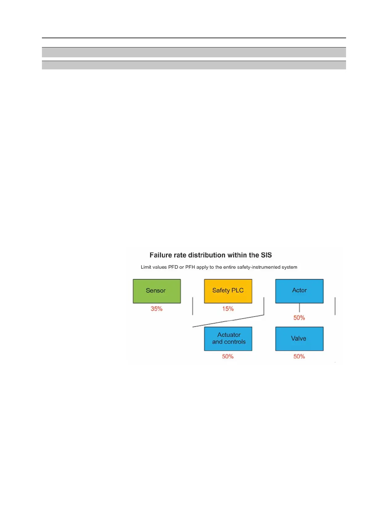
Figure 15: Non-normative failure distribution assumed by AUMA
Information System power supply has not been considered for calculating the figures for actuator
and actuator controls.
As previously mentioned in the architecture section, safeguarding power supply and
resulting calculations are the responsibility of the plant operator.
The plant operator is responsible for complying with assumed MTTR. Otherwise the
data of the quantitative results is no longer valid.
35
Multi-turn actuators
SA 07.2 – SA 16.2/SAR 07.2 – SAR 16.2 Safety-related figures

 Loading...


