Information
●
For loop topology, automatic termination is performed as soon as the AUMATIC
is connected to the power supply.
●
In case of a power outage of the AUMATIC, the two RS-485 loop segments will
be automatically connected so that the actuators following these segments re-
main available.
●
When using a SIMA master station, a redundant loop topology may be estab-
lished.
Connect fieldbus cables:
1. Connect fieldbus cables.
2. If the actuator is the final device in the fieldbus segment (line topology only):
2.1 Connect termination resistor for channel 1 through linking the terminals
31 - 33 and 32 - 34 (standard)
2.2 For AUMA redundancy I or II: Connect termination resistor for channel 2
through linking the terminals 35 - 37 and 36 - 38.
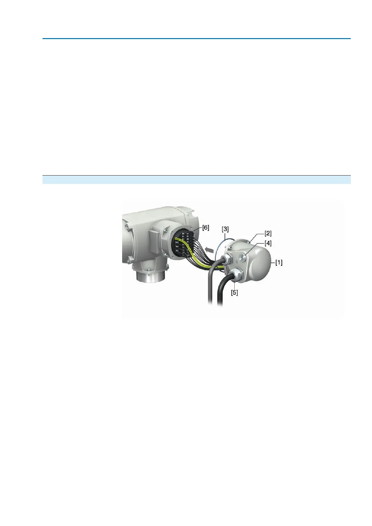
5.2.4. Terminal compartment: close
Figure 25: Close terminal compartment
[1] Cover (figure shows KP version)
[2] Screws for cover
[3] O-ring
[4] Blanking plugs
[5] Cable gland
[6] Flameproof frame
1. Clean sealing faces of cover [1] and frame [6].
2. Check whether O-ring [3] is in good condition, replace if damaged.
3. Apply a thin film of non-acidic grease (e.g. petroleum jelly) to the O-ring and
insert it correctly.
4. Fit cover [1] and fasten screws [2] evenly crosswise.
5. Fasten cable glands and blanking plugs applying the specified torque to ensure
the required enclosure protection.
31
SAVEx 07.2 – SAVEx 16.2 / SARVEx 07.2 – SARVEx 16.2 Control unit: electronic (MWG)
ACVExC 01.2 Non-Intrusive Modbus RTU Electrical connection