Flameproof enclosure, danger of explosion!
Risk of death or serious injury.
→
Before opening, ensure that there is no explosive gas and no voltage.
→
Wait for 30 seconds after power cut-off prior to opening the housing.
→
Handle cover and housing parts with care.
→
Joint surfaces must not be damaged or soiled in any way.
→
Do not jam cover during fitting.
Open
1. Loosen screws [2] and remove cover [1] from the switch compartment.
Close
2. Clean sealing faces of housing and cover.
3. Preserve joint surfaces with an acid-free corrosion protection agent.
4. Check whether O-ring [3] is in good condition, replace if damaged.
5. Apply a thin film of non-acidic grease (e.g. petroleum jelly) to the O-ring and
insert it correctly.
6. Place cover [1] on switch compartment.
7. Fasten screws [2] evenly crosswise.
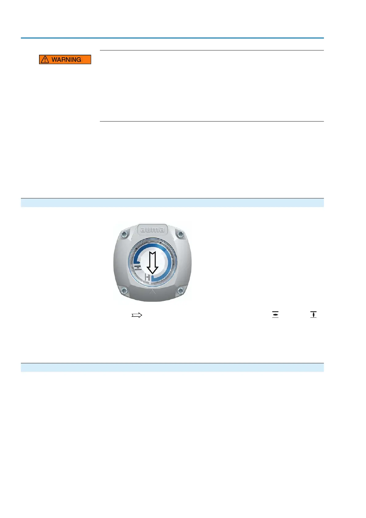
10.2. Mechanical position indicator (self-adjusting)
Figure 81: Mechanical position indicator (self-adjusting)
The self-adjusting mechanical position indicator shows the valve position by means
of an arrow . When correctly set, the arrow points to symbol (OPEN) or
(CLOSED) in the end positions.
Information
The position indications is housed in the actuator switch compartment. Opening the
switch compartment for manual setting is only necessary if the gear stage setting
must be modified of if the factory settings of predefined end position CLOSED (or
OPEN) must be adapted when commissioning.
10.2.1. Mechanical position indicator: set
1. Move valve to end position CLOSED.
72
SAVEx 07.2 – SAVEx 16.2 / SARVEx 07.2 – SARVEx 16.2 Control unit: electronic (MWG)
Commissioning (settings/options in the actuator) ACVExC 01.2 Non-Intrusive Modbus RTU