Information
●
For loop topology, automatic termination is performed as soon as the AUMATIC
is connected to the power supply.
●
In case of a power outage of the AUMATIC, the two RS-485 loop segments will
be automatically connected so that the actuators following these segments re-
main available.
●
When using a SIMA master station, a redundant loop topology may be estab-
lished.
Connect fieldbus cables:
1. Connect fieldbus cables.
2. If the actuator is the final device in the fieldbus segment (line topology only):
2.1 Connect termination resistor for channel 1 through linking the terminals
31 - 33 and 32 - 34 (standard)
2.2 For AUMA redundancy I or II: Connect termination resistor for channel 2
through linking the terminals 35 - 37 and 36 - 38.
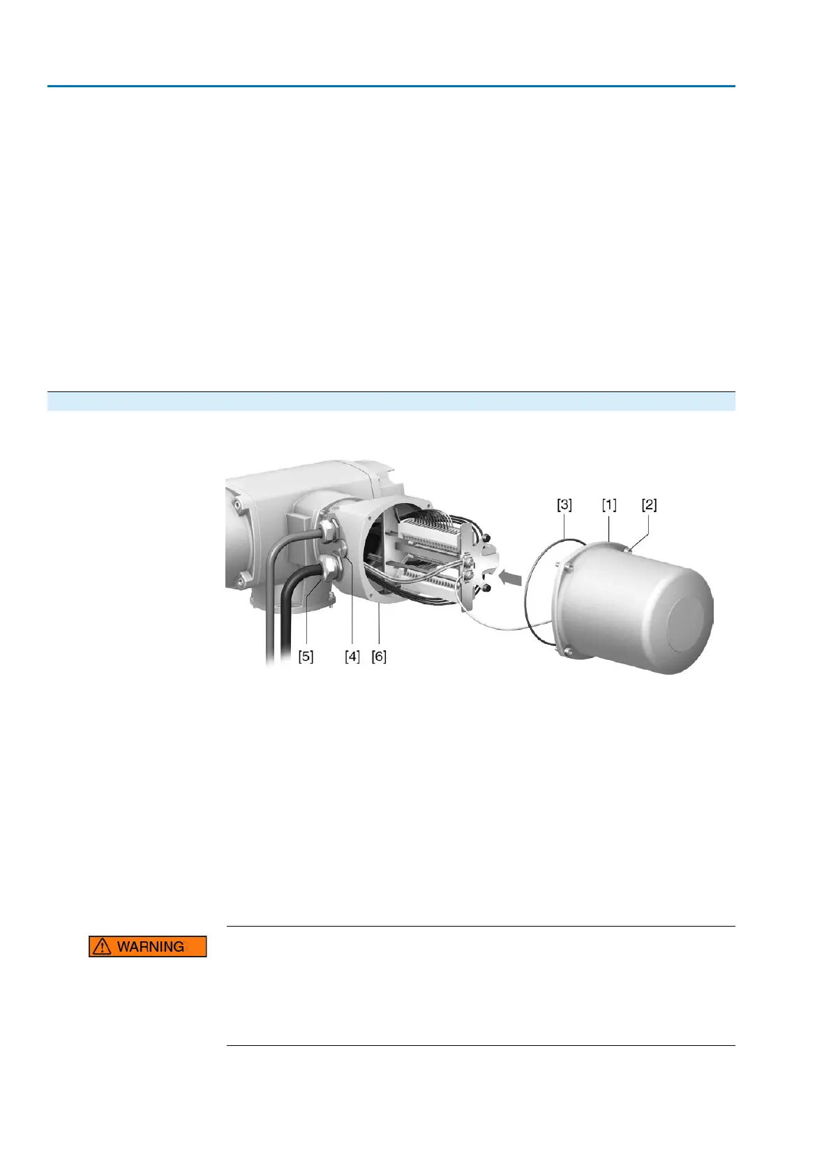
5.3.4. Terminal compartment: close
Figure 32: Close terminal compartment
[1] Cover (illustration shows type of protection Ex e)
[2] Screws for cover
[3] O-ring
[4] Blanking plugs
[5] Cable gland (example)
[6] Connection frame
1. Clean sealing faces of cover [1] and connection frame [6].
2. For Ex plug/socket connector designed as KES flameproof: Preserve joint sur-
faces with an acid-free corrosion protection agent.
3. Check whether O-ring [3] is in good condition, replace if damaged.
4. Apply a thin film of non-acidic grease to the O-ring and insert it correctly.
Flameproof enclosure, danger of explosion!
Risk of death or serious injury.
→
Handle cover and housing parts with care.
→
Joint surfaces must not be damaged or soiled in any way.
→
Do not jam cover during fitting.
5. Fit cover [1] and fasten screws [2] evenly crosswise.
36
SAVEx 07.2 – SAVEx 16.2 / SARVEx 07.2 – SARVEx 16.2 Control unit: electronic (MWG)
Electrical connection ACVExC 01.2 Non-Intrusive Modbus RTU