9
3 Installation
3.1 Electrical Design
3.1.1 Upstream Wiring
Chargers are considered continuous load devices (EVs draw maximum load for long durations);
therefore, electrical branch circuits must be sized at 125% of the load for North American installations,
in accordance with National Electric Code (NEC) requirements. (For other regions, refer to local code.)
This means that for a maximum 80 A load at 208/240 V output to an electric vehicle, 100 A breaker is
required.
Wiring must be sized in accordance with NEC requirements for continuous load devices. Typically, 3
AWG (26.67 mm
2
) insulated electrical wire is used, depending upon the rating of the circuit and the
distance between the electrical panel and the charger. The AC input terminal block accepts a maximum
of 2 AWG (33.63 mm
2
).
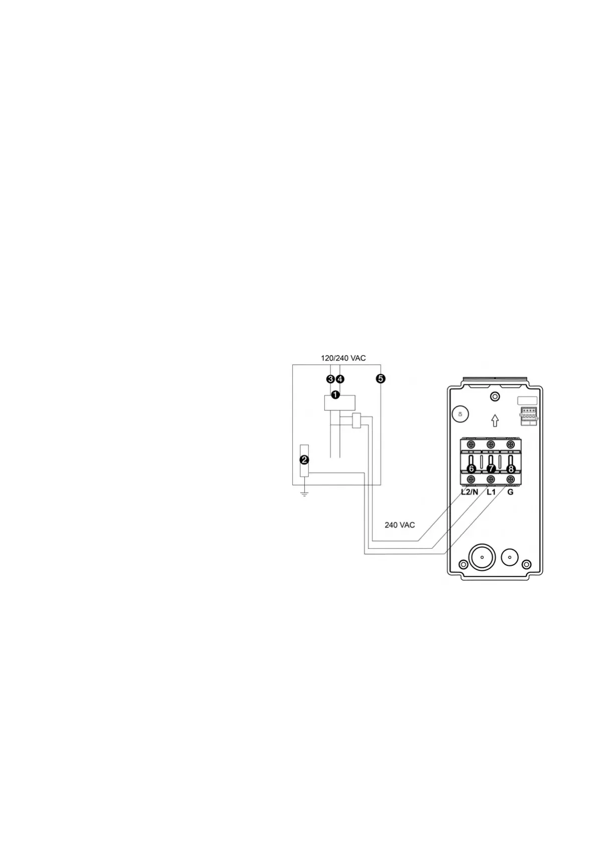
240 VAC Panel
1. Main Breaker
2. PE Bus
3. L1
4. L2
5. Local Service or Sub Panel
6. L2/N
7. L1
8. Ground/PE