20
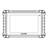
3.4.3 RS485 Cable Connection (Optional)
1.
Use a flathead screwdriver to
press and hold the buttons (1)
above the connector holes on the
RS485 terminal block.
2.
Strip the RS485a and RS485b
cables to 1/3” (8 mm) and push
them into the holes as indicated.
Release the buttons and then
secure the cables by tightening
the screws to 5 lbf·in (0.57 Nm)
using a flathead screwdriver with
the tip size being 1/8” (3 mm) x
1/40” (0.6 mm).
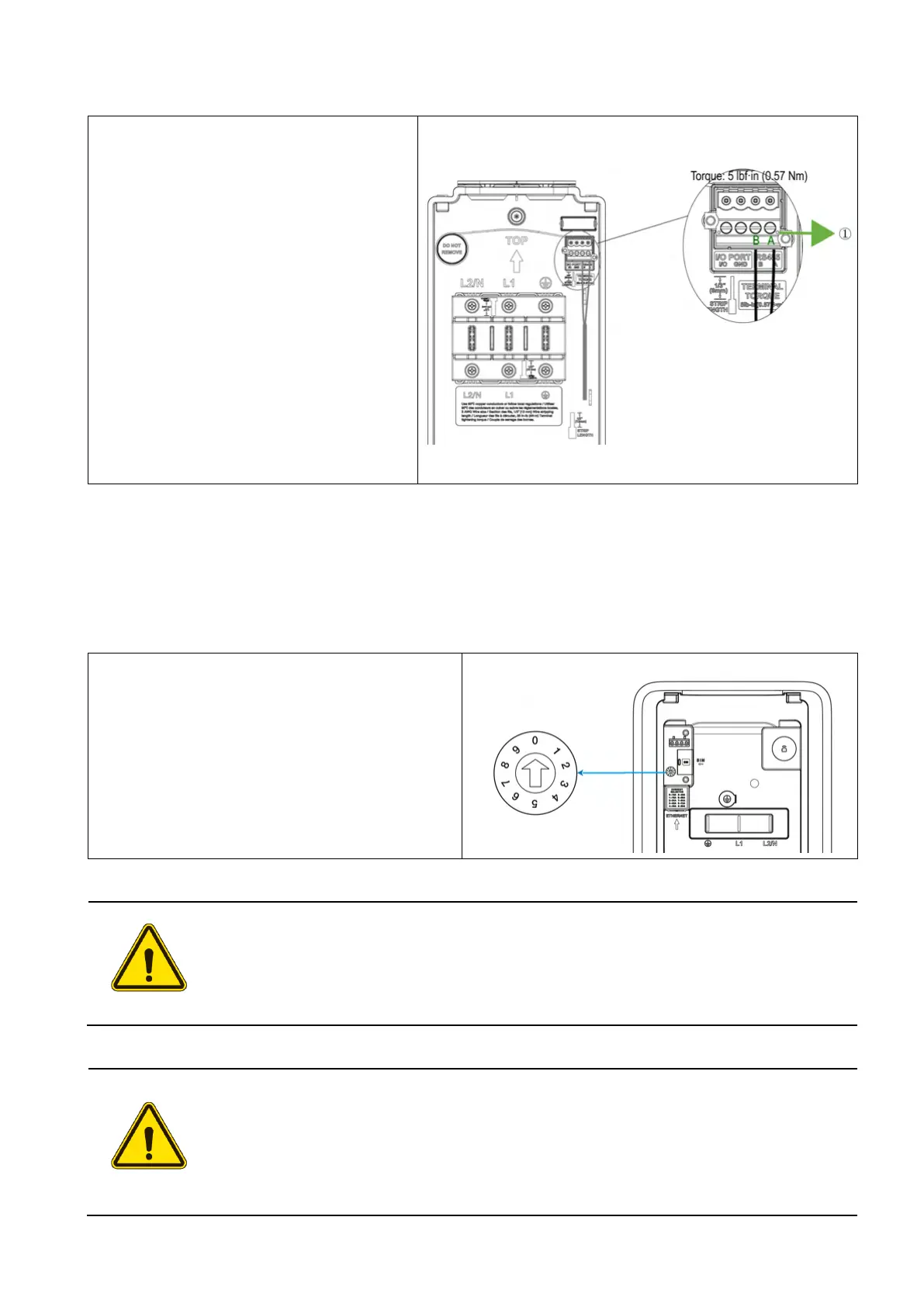
3.5 Adjusting the Rated Current (Optional)
This charger allows you to manually set a lower maximum current using the built-in current selector
when installing the charger on a circuit rated lower than the maximum rating for the charger.
Locate the current selector on the back of
the main unit. Then u
screwdriver with the tip size being 1/8” (3
mm) x 1/40” (0.6 mm) to set the DIP switch
to the appropriate position per the table
below.
CAUTION
To reduce the risk of fire, only connect the charger to a circuit with a branch circuit
over-current protection of 125% of the selected maximum amperage setting of
the device in accordance with ANSI/NFPA 70 (US) CSA C22.1 (Canada).
ATTENTION
Pour réduire le risque d'incendie, ne branchez la borne de recharge que sur un
circuit doté d'une protection contre les surintensités de 125 % de l'intensité
maximale sélectionnée pour l'appareil, conformément à la norme ANSI/NFPA 70
(États-Unis) et à la norme CSA C22.1 (Canada).