Autic System Marine PC Rev. 1.1 Page 16
ELECTRICAL INSTALLATION
The Panel PC is certified for the connection to grounded power supply according to
EN60950. The panel PC’s shall be supplied by the standard power adapter or by
another galvanically isolated supply of approved type.
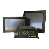
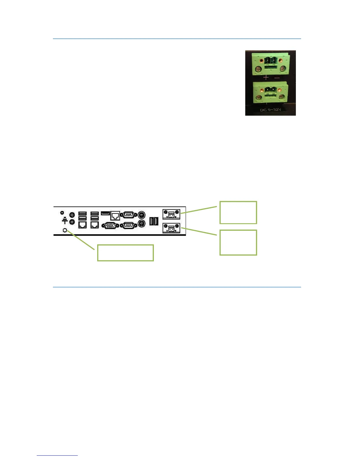
There are two power connectors allowing the use of two individual power sources
to obtain redundancy. One power connector can be used for single input. Operating
voltage is from 9 to 32 VDC. Be aware of the current consumption for wire
dimension when using low supply voltage. Total power consumption can be up to 80
W.
The power input has polarity protection if + and – should be interchanged during installation.
Data cables connected to the unit should to be of the shield type.
We recommend that the shield is connected to ground on both sides.
We recommend using min. 4 mm² grounding wire.
Isolate PCB ground (0 V) from chassis ground (earth).
Signal ground (0 V) is isolated from chassis ground.
NOTE! Make sure the power is off when connecting and disconnecting the connectors.
VERIFICATION
Please observe the following during installation and startup.
1) Be accurate when mounting the gasket tape between the front bezel and the panel.
2) Cover the ventilation holes with a piece of paper to prevent metal shavings from entering the unit.
Remove again after installation to ensure sufficient ventilation.
3) Ground the unit according to installation instruction.
4) Make sure the polarity is correct for power connection before connecting to power outlet.
5) Keep signal cable and high voltage cable separated.
6) After power on, make sure that the system performs a normal startup of the OS.
7) The system may be delivered with a 30 day trial version of Windows OS. Make sure you have a valid
OS.
 Loading...