SE6166 Controller • Rev. 4/13/2011 8 © 2011 Automated Logic Corporation
1 Verify that the SE6166's power and communications connections work properly.
2 Turn off the SE6166's power.
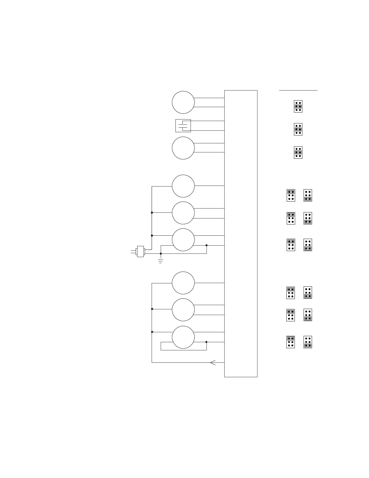
3 Connect the input wiring to the screw terminals on the SE6166.
Dry
contact
Any input
Gnd
Gnd
External
24 Vdc
half-wave
power
supply
2 wire
3 wire
Aux Power Out
+24 Vdc
200 mA max
Out
Gnd
V+
Gnd
+
Any input
Gnd
+
Any input
Gnd
+
Any input
+
Gnd
Any input
+
Gnd
Any input
+
Any input
+
Set Universal
Input Mode
Select jumper to...
Thermistor
Dry-contact
RTD
Out
Gnd
V+
Any input
+
Volts
Volts
Volts
Volts
Volts
Volts
mA
mA
mA
mA
mA
mA
10 kOhm
thermistor
1 kOhm
RTD
n/c
4 wire
2 wire
3 wire
4 wire
Out +
Out -
Gnd
V+
Gnd
Any input
+
Out
V+
Gnd
Out
V+
n/c
Out +
Out -
V+
Gnd
0-5 Vdc,
0-10 Vdc,
or
4-20 mA
0-5 Vdc,
0-10 Vdc,
or
4-20 mA
0-5 Vdc,
0-10 Vdc,
or
4-20 mA
0-5 Vdc,
0-10 Vdc,
or
4-20 mA
0-5 Vdc,
0-10 Vdc,
or
4-20 mA
0-5 Vdc,
0-10 Vdc,
or
4-20 mA
or
or
or
or
or
or
NOTES
○ Connect the shield wire to the GND terminal with the ground wire.
○ Use only IN-1 or IN-2 for pulse counter or timed local override.
○ For a loop-powered 4-20 mA sensor, wire the sensor's positive terminal to the +
terminal on the SE6166's
Aux Power Out connector. Wire the sensor's negative
terminal to an input's
+ terminal.
To wire inputs
and outputs