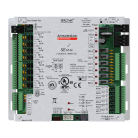
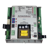
SE6166 Controller • Rev. 4/13/2011 7 © 2011 Automated Logic Corporation
5 If the SE6166 is at either end of a network segment, connect a BT485 to the
SE6166.
6 Turn on the SE6166's power.
7 Verify communication with the network by viewing a Module Status report in
WebCTRL.
Input wiring
0–5 Vdc
0–10 Vdc
1000 feet
(305 meters)
26 AWG Shielded
0–20 mA 3000 feet
(914 meters)
26 AWG Shielded or
unshielded
Thermistor
Dry contact
Pulse counter
TLO
1000 feet
(305 meters)
22 AWG Shielded
RTD 100 feet
(30 meters)
22 AWG Shielded
RS sensor
LogiStat sensor
See Wiring a room sensor to the SE6166 (page 10).
NOTE ALC recommends use of an external current transducer between an RTD and the
SE6166.
Output wiring
To size output wiring, consider the following:
• Total loop distance from the power supply to the controller, and then to the controlled
device
NOTE Include the total distance of actual wire. For 2-conductor wires, this is twice the
cable length.
• Acceptable voltage drop in the wire from the controller to the controlled device
• Resistance (Ohms) of the chosen wire gauge
• Maximum current (Amps) the controlled device requires to operate
Wiring inputs and outputs
Wiring
specifications