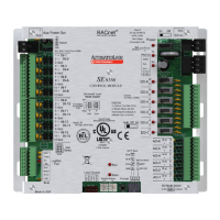
SE6166 Controller • Rev. 4/13/2011 14 © 2011 Automated Logic Corporation
Thermistor
Select your Thermistor type
or set up and select a
2
N/A
3
Pulse Counter
N/A N/A
Dry Contact
N/A N/A
1
The sensor reads a value and sends a corresponding signal (Volt, mA, or psi) to the SE6166's
physical input. The Analog Input microblock uses the Min and Max values to linearly translate the
signal into the engineering value used in subsequent control logic. For example, set
Min to 0 and
Max to 10 for a 4–20 mA sensor that measures velocity from 0.0 to 10.0 inches/second so that
when the input reads 4 mA, the microblock outputs a value of 0. Similarly, when the input reads 8
mA, the microblock outputs a value of 2.5.
2
You can set up a custom translation table (page 19) on the driver's Custom Translation Tables
pages in WebCTRL.
3
The control program must have one Pulse to Analog Input microblock for each pulse counting
input.
0-10 Vdc
Engineering values
associated with 0 Vdc
(Min) and 10 Vdc (Max)
1
2-10 Vdc
Linear w/Offset,
2–10 Volts
Engineering values
associated with 2 Vdc
(Min) and 10 Vdc (Max)
1
0-20 mA
Engineering values
associated with 0 mA
(Min) and 20 mA (Max)
1
4-20 mA
Engineering values
associated with 4 mA
(Min) and 20 mA (Max)
1
Relay
N/A N/A
1
The Analog Output microblock uses the Min and Max values to linearly translate its EIKON
LogicBuilder wire value into a physical output signal (Volt, mA, or psi) sent from the SE6166 to an
actuator. For example, set
Min to 0 and Max to 100 for an Analog Output microblock that
receives a 0 to 100% open signal from a PID microblock and that controls a 0–10 Vdc actuator
so that when the PID signal is 100%, the SE6166 output is 10 Vdc. Similarly, when the PID signal
is 50%, the SE6166 output is 5 Vdc.
Output values