SE6166 Controller • Rev. 4/13/2011 10 © 2011 Automated Logic Corporation
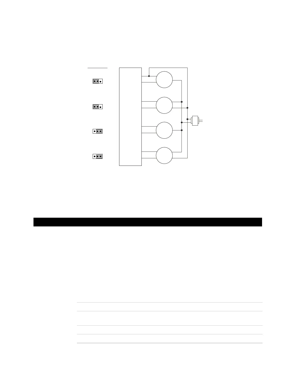
6 Connect the analog output wiring to the screw terminals on the SE6166 and to the
controlled device.
Any AO
Gnd
Gnd
24 Vac/dc
+
+
–
–
Gnd
0-10 V
0-10 V
Hot
Hot
Gnd
4-wire
3-wire
+
Any AO
+
Set AO
Mode Select
jumper to...
0-10 Vdc
0-20 mA
Gnd
+
–
0-20 mA
0-20 mA
Hot
3-wire
Any AO
+
Gnd
+
–
Hot
Gnd
4-wire
Any AO
+
0-10 Vdc
0-20 mA
7 Set the AO Mode Select jumper to the type of device you are wiring the output to.
8 Turn on the SE6166's power.
You can wire:
• An RS Standard, RS Plus, RS Pro, or RS Pro-F to the SE6166's Rnet port
• A LogiStat or LogiStat Plus to the SE6166's Lstat port
See the following sections for wiring instructions. For other details, see the RS Room
Sensors Technical Instructions or the LogiStat Sensors Technical Instructions.
NOTE Use the specified type of wire and cable for maximum signal integrity.
Description 4 conductor, shielded or unshielded, CMP, plenum rated cable
Conductor 22 AWG (7x0096) bare copper if Rnet has only RS sensors.
18 AWG (7x0152) bare copper if Rnet has a BACview.
Maximum length 500 feet (152 meters)
Insulation Low-smoke PVC (or equivalent)
Wiring a room sensor to the SE6166
Rnet wiring
specifications