4 Connections and Insulation Block Diagram
© Copyright Reserved Autonics Co., Ltd. 33
4.3 Wiring precautions
Mixing up the input terminals with output terminals and vice versa can lead to product
damage.
Use only sensors supported by the product.
Make sure to connect rated SSRs or loads to the output terminals.
Make sure to connect the communication cable with correct communication terminals (A, B).
Make sure to observe correct polarity of power source terminals. (+ and -).
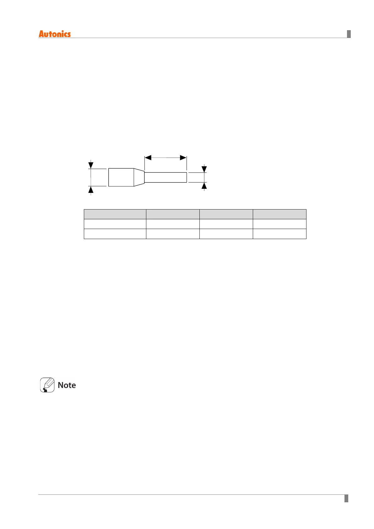
Use crimp terminals of size specified below.
1 to 12 10mm
Max. 1.7mm Max. 3.7mm
13 to 22 10mm
Max. 2.1mm Max. 4.2mm
4.3.1 Sensor connection
(1) Compensation wire connection
For thermocouple sensors, use compenstion wire of the same specification as input sensors.
Using an extension wire of different specification and/or material will increase inaccuracy of
temperature sensing. It is recommended to choose high performance compensation wire for
more reliable sensing.
(2) Measurement error
Do not mix up the direction of the input sensor connector.
Carefully adjust both load and sensor positions.
Make sure the sensor is securely attached to the input connector.
(3) Wiring with AC power lines
Do not put the sensor lines in close proximity of the AC power lines.
Make sure the sensor is completely inserted in the connector using a crimped terminal.
Fix the sensor to the connecter properly for accurate measurement.
b