10
of the loop is level with the drain line connection. This
will provide an adequate siphon trap.Where a drain
empties into an overhead sewer line, a sink-type trap
must be used. Secure the end of the drain line to
prevent it from moving (Figure-11).
Brine Line Connection
It is recommended that separate brine
lines be used for each tank.
A regenerant tank aircheck is not required when using a
255 valve with the built-in aircheck. Doing so will cause
premature checking and may result in hard water or
regenerant tank overflow. The 255 aircheck is available
standard with a 1/4" NPT tube compression fitting. The
use of Teflon tape is required on the 1/4" NPT
connection.
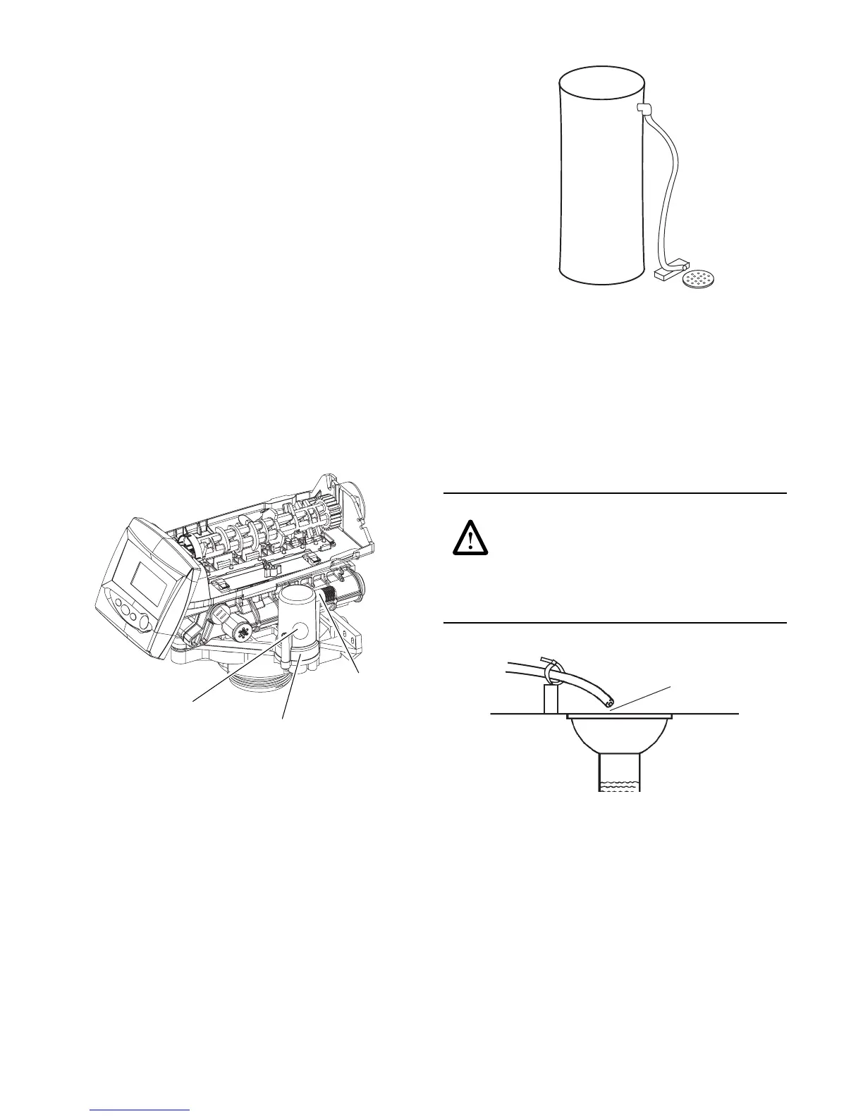
Install an appropriate fitting onto the 1/4-inch male NPT
connection on the air check (Figure-9), and install a
length of 3/8-inch polyethylene tubing between the air
check fitting and the brine pick-up tube at the brine tank.
If you are using a brine valve remove the ball in the air
check to avoid possible premature checking.
Figure 9
Note: Make sure that all fittings and connections are
vacuum tight so that premature checking does not take
place. Premature checking occurs when the ball in the
air check falls to the bottom before all brine is drawn
out of the brine tank.
Brine Tank Overflow Line Connection
In the event of a malfunction, the brine tank overflow
connection directs overflow to the drain instead of
spilling it on the floor where it could cause water
damage. Complete the following steps to connect the
overflow fitting to the brine tank:
1. Locate the fitting hole on the side of the brine tank.
2. Insert the overflow fitting (not supplied) into the tank
and tighten with the plastic thumb nut and gasket as
illustrated in Figure-10.
Figure 10 Brine Tank Drain
3. Attach a length of 1/2-inch (1.3-cm) tubing (not
supplied) to the fitting and run to the drain.
Note: Do not elevate the overflow line higher than
3 inches (7.6 cm) below the bottom of the overflow
fitting. Do not tie into the drain line of the control unit.
The overflow line must be a direct, separate line from
the overflow fitting to the drain, sewer, or tub. Allow an
air gap as in the drain line connection, Figure-10.
WARNING:
Never insert drain line directly
into a drain, sewer line, or trap (Figure-11).
Always allow an air gap between the drain line
and the waste water to prevent the possibility
of sewage being back-siphoned into the
conditioner. Secure the end of the drain line to prevent
it from moving (Figure-11).
Figure 11
Brine Tank
Normally one brine tank is needed for each tank
.
The
use of block salt or rock salt is not recommended. If a
brine shelf is used, two brine tanks are required. This is
due to the increased time needed to produce a
concentrated brine solution when using a salt shelf. If
rapid multiple exhaustions and regenerations are
anticipated, do not use a salt shelf even if two brine
tanks are used.
Check Ball
Air Check
Regenerant Tank
Tube Connection
Drain
Air Gap
 Loading...