14
Camshaft Cycle Positions
The front end of the camshaft has an indicator cup. The
cup has slots in the outer edge and cycle numbers on
the inside face (Figure-12).
Remove the cover and look over the top of the 764
control to view the cycle numbers. The number at the
top indicates the current cycle position of the control
valve. The corresponding slot for the number is
positioned at the optical sensor, which is rotated
approximately 90 degrees out of phase.
Note: If electrical power is not available, the camshaft
can be rotated counterclockwise by hand if the motor is
removed.
Cycle Indicators:
0 = Treated Water
1 = Backwash Cycle
2 = Regenerant Draw Cycle
3 = Slow Rinse Cycle
4 = System Pause
5 = Fast Rinse Cycle 1
6 = 2
nd
Backwash
7 = 2
nd
Fast Rinse
8 = Regenerant Refill
Figure 12
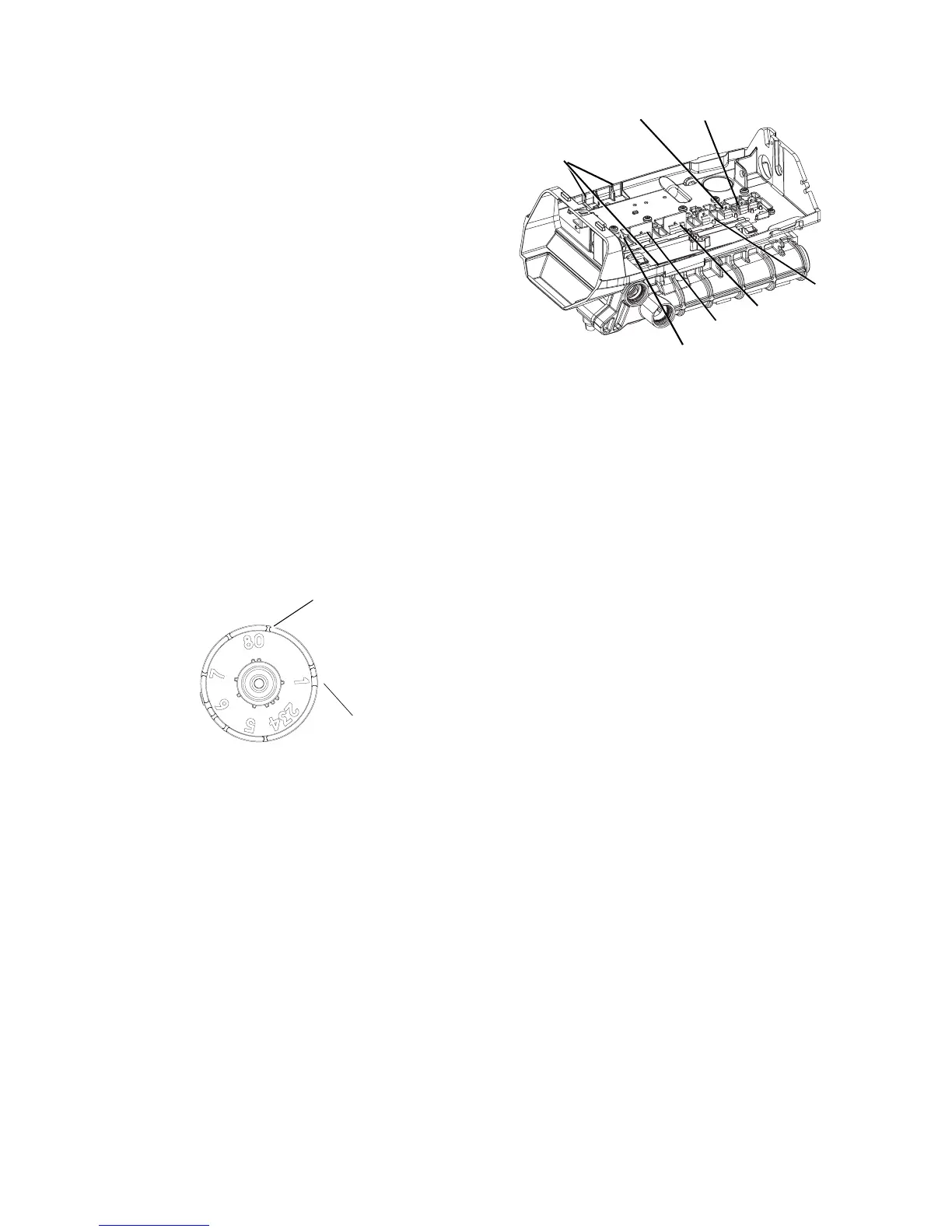
Valve Disc Location/Function
Figure 13 255 Valve
764 Control Operation
Power Loss Memory Retention
The 764 control features battery-free Time of Day and
Day of Week retention during loss of power. A super
capacitor is designed to keep time for 8 to 24 hours
depending on the installation. If the super capacitor is
exhausted the Logix control will display four dashes
(- - :- -) immediately upon power up. The Time of Day
and Day of Week must be reset.
All other programmed parameters are stored in the
static memory and are retained.
Treated Water
Treated Water
Cycle Number
Slot
5 Rinse Drain
6 Backwash/Drain
4 Bypass
3 Outlet
2 Inlet
1 Regenerant
Wiring
Breakouts
 Loading...