15
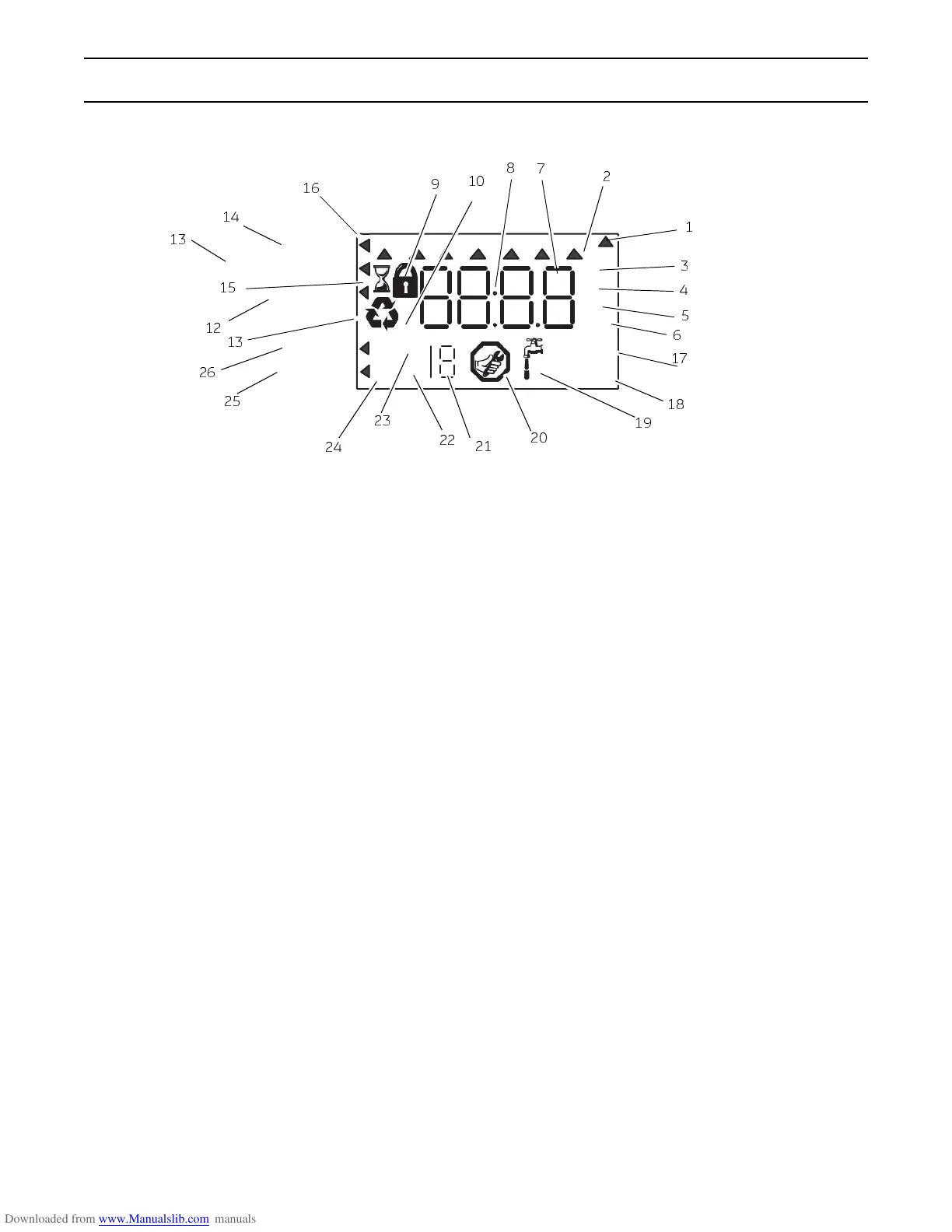
Display Icons & Cursors
Note: In normal operation and during programming,
only a few of the icons will actually be displayed.
1. This cursor is displayed when the days between
regeneration are being programmed (used with .5
to 99 day regeneration programming).
2. One of these cursors is displayed to indicate which
day will be programmed into the controller.
3. "PM" indicates that the time displayed is between
12:00 noon and 12:00 midnight (there is no AM
indicator). PM indicator is not used if clock mode is
set to 24-hour.
4. When "MIN" is displayed, the value entered is in
minute increments.
5. When g/L is displayed, the value for regenerant
amount entered is in grams/Liter.
6. When "Kg" is displayed, the value entered is in
kilograms or kilograins.
7. Four digits used to display the time or program
value. Also used for error codes.
8. Colon flashes as part of the time display. Indicates
normal operation (742 only).
9. Locked/unlocked indicator. In Level I programming
this is displayed when the current parameter is
locked-out. It is also used in Level II programming
to indicate if the displayed parameter is locked
(icon flashes) when controller is in Level I.
10. When "x2" is displayed, a second regeneration has
been called for.
11. The recycle sign is displayed (flashing) when a
regeneration at the next time of regeneration has
been called for. Also displayed (continuous) when
in regeneration.
12. The display cursor is next to "SALT AMOUNT"
when programming the amount of regenerant. If
the controller is on a 3-cycle filter then backwash
time is programmed.
13. The display cursor is next to "REGENERATION
TIME" when programming the time of regeneration
and the days of regeneration.
14. The display cursor is next to "TIME/DAY" when
programming the current time and day.
15. The hourglass is displayed when the motor is
running. The camshaft should be turning.
16. These cursors appear next to the item that is
currently displayed.
17. X100 multiplier for large values.
18. When Lbs/ft
3
is displayed the value for regenerant
amount entered is in pounds/cubic foot.
19. Faucet is displayed when the current flow rate is
displayed. Control may show the faucet and "0",
indicating no flow.
20. Maintenance interval display turns on if the months
in service exceed the value programmed in P11.
21. Used with #24, #25, and #26. Displays valve in
service, a sequence number or a value.
22. History Values (H). The number displayed by #23
identifies which history value is currently displayed.
23. Parameter (P). Displayed only in Level II
Programming. The number displayed by #23
identifies which parameter is currently displayed.
Time/Day
Regeneration Time
Salt Amount
Capacity
SU MO TU WE TH
FR
SA DAYS
Hardness
a
a
a
If your Logix 764 controller was
purchased as a filter control, the
overlay will show: Time/Day,
Backwash Time, Backwash Length
and Capacity.
g/L
PM
MIN
KGx2
x100P
HC
Lbs/ft
3
1
3
4
5
21
22
23
7
25
8
15
9
10
20
19
18
17
2
6
24
26
13
12
13
14
16
 Loading...