24
Level II Programming – P Values
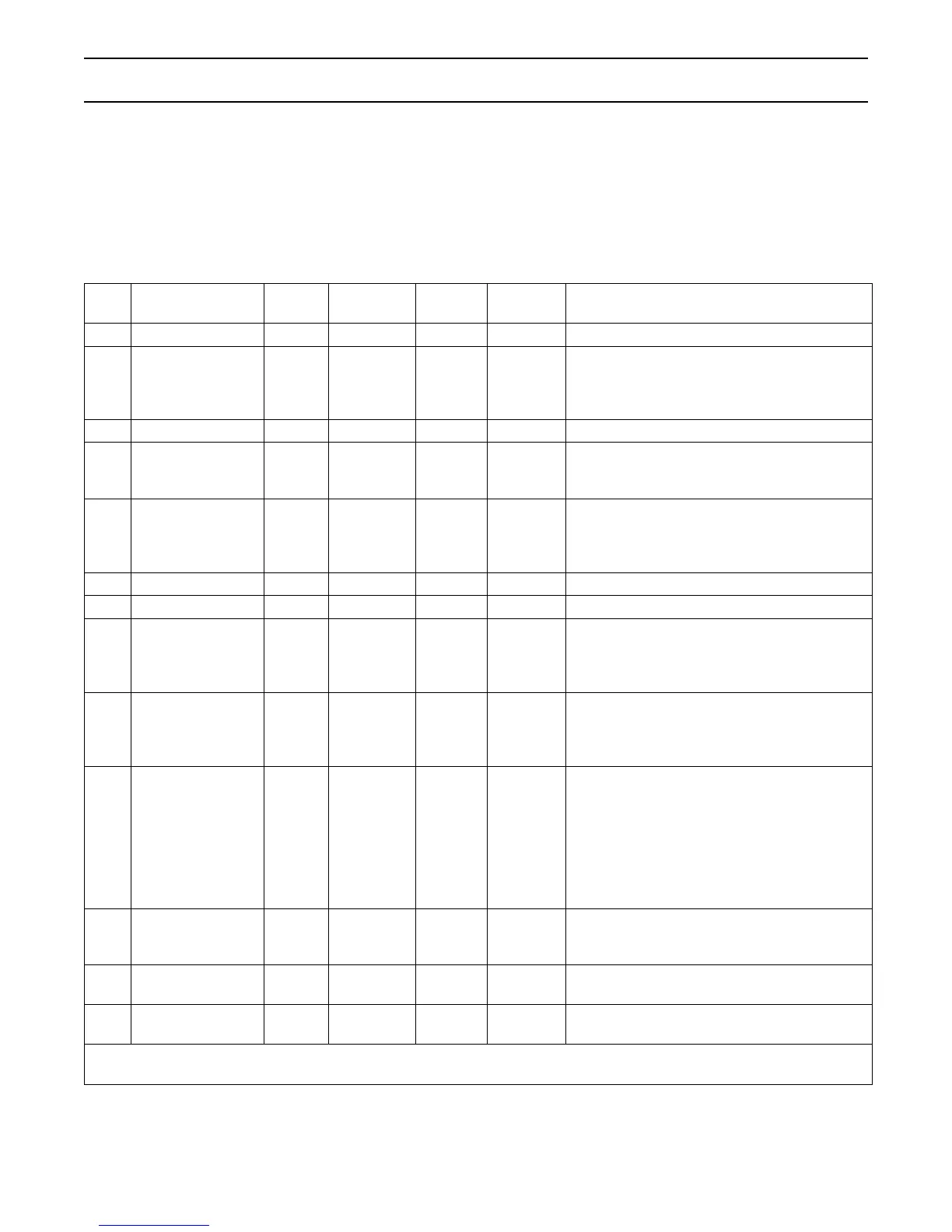
Level II program parameters can be adjusted to fine-
tune the conditioner’s operation. The parameters are
accessible by pressing and holding the UP and DOWN
buttons until the control displays a “P” value. Note: The
control must be in the home position to change settings.
See Table-3 for Level ll parameters. Typically the
Level ll parameters will not need to be adjusted as the
default settings accommodate most applications.
Contact your Water Treatment Professional before
attempting any programming.
Table-3
*Not used when control is programmed for twin
alternating
Description Range
Minimum
Increments
Default Units Notes
P9 Units of Measure 0-1 1 (2) 0 = US 1 = Metric
P10 Clock Mode 0-1 1 (2)
0 = 12 hour clock; flow rate service display
1 = 24 hour clock; flow rate service display
2 = 12 hour clock; Time of Day service display
3 = 24 hour clock; Time of Day service display
P11 Service Interval 0-250 1 0 Months Uses 30 days for each month; 0 = off
P12
Remote
regeneration switch
delay
3-250 1 60 seconds
Time remote switch must be active to start
regeneration.
P13
Chlorine Generator
Options
(not used on “A”
and “P” systems)
0-2 1 0
0 = No chlorine generator
1 = salt check only
2 = generate chlorine
P14 Refill Rate 1-700 1 (1) gpm x 100
P15 Draw Rate 1-700 1 (1) gpm x 100
P16
Reserve Type
(not used for
alternating mode)
0-3 1 0
0 = variable reserve delayed regeneration
1 = fixed reserve delayed regeneration
2 = variable reserve immediate regeneration
3 = fixed reserve immediate regeneration
P17
Initial average or
fixed reserve
(not used for
alternating mode)
0-70 1 30
% of
Capacity
Depends on value entered in P16
P18 Flow sensor select 0-7 1 (1)
0 = internal magnum NHWB,
1, 6 = 1" Autotrol turbine
2, 7 = 2" Autotrol turbine
3 = User defined K-factor
4 = User defined Pulse Equivalent
5 = Internal Magnum HWB
Values 6 & 7 are for single turbine
configurations on twin alternating systems.
P19
K-factor or Pulse
equivalent
1.00-
99.99
0-9999
0.01
1
0.01
1
K-factor P18=3;
Pulse Equivalent P18 = 4
Pr Refill First * 0-1 1 0
0 = Refill first off
1 = Refill first on
Pd
Remote switch
operation
0-1 1 0
0 = Immediate Regeneration after P12 time
1 = Delayed Regeneration after P12 time
Notes: (1) Default selected with valve type and resin volume.
(2) Factory Default is "0” for North America units and "1” for World units.