21
B. C2 will be displayed. With the control in this
position, check that the water is being drawn out
of the regenerant tank. The water level in the
regenerant tank should recede very slowly.
C. Observe that water is being drawn from the
regenerant tank for at least three minutes. If the
water level does not recede, check all
regenerant line connections for air leaks.
8. If the water level is receding from the regenerant
tank you can quick cycle the control to the C8
Regenerant tank refill position.
A. The control will cycle to the regenerant tank refill
cycle, and water will be directed down through
the regenerant line to the regenerant tank. Let
the water flow through the line until all air
bubbles have been purged from the line. Note:
Do not let the water flow down the line to the tank
for more than one to two minutes, or the tank
may overfill.
9. Repeat steps 4 and 8 for each additional tank.
10. Finally, turn on a faucet plumbed after the water
conditioner. Run the faucet until the water runs
clear.
11. Add the appropriate amount of regenerant to
regenerant tank.
The Water Conditioning System is
Now Fully Operational
Note: After any control reset (valve type or system
change, etc.) it is necessary to initiate a manual
regeneration and quick cycle through it. This will
ensure the control and cam are synchronized. If not
synchronized
err# will display and the control will
drive cams to the correct position for valve and system
type programmed.
Quick Cycling the Control for 255A
Systems
It is required that the control be quick cycled to specific
regeneration cycles when placing the conditioner into
operation. This will ensure that all of the air in the tank
and valve is purged. The process also provides a check
for leaks and functioning of the brine system.
After the initial power up and programming, tank 1 will
be in standby and tank 2 will be in service.
Before the final filling of the media tanks with water,
check that:
– the nearest water faucet is completely closed.
– the valve drain line is properly routed to a drain.
– the regenerant tank is empty and the regenerant
hose is connected to the valve.
– the water supply valve is partially open
– valve bypasses are in service positions.
During this process the valves will need to be quickly
advanced to the next cycle. To quick cycle press
and after the regeneration cycle has started.
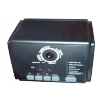
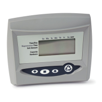
255 Alternating tank systems have one Logix 764
control that is mounted on tank 1. Tank 2 has a blank
faceplate and the tank 2 valve is controlled by the Logix
764 control on tank 1.
To Place the 255 Alternating System
into Operation:
1. Press and hold the button for 5 seconds. This
will start the first regeneration.
Note: Once the valve has reached the cycle (visable
on the display and camshaft has stopped turning),
quick cycle to the next cycle. This is especially
recommended for the C8 cycle. Overfilling the
regenerant tank will affect the brine and future regen
cycles.
Note: It is recommended that you do not put
regenerant into the tank until after the control valve has
been put into operation. With no regenerant in the tank,
it is much easier to view water flow and motion in the
tank.
Tank 1 moves through cycles:
C5 - Fast Rinse
As water enters the tank, air will be forced out
the drain line. Once water fills the tank it will
then discharge out the drain line. Quick cycling
the control can now be used to advance
through the remaining cycles
C8 - Regenerant Refill; the aircheck is filled and
flow to the regenerant tank is visable
Quick cycle Tank 1 to service
then--
 Loading...