Avantik Cryostat QS11 / QS11UV
Avantik
36 Commerce St.
Springfield NJ 07081 / USA
387 779 - English
15
Warning:
The instrument must only be moved in
standing or slightly tilted (approx. 30°)
position.
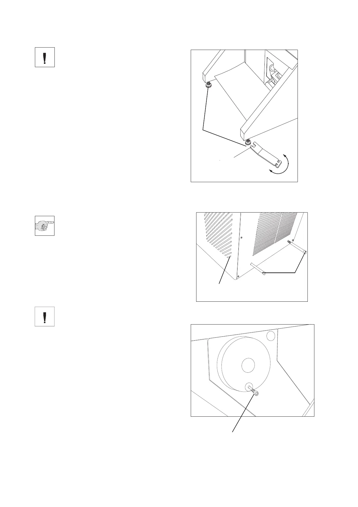
Choose installation site that
• enough ventilation for the cooling system is
guaranteed.
• the distance between wall and rear panel is
approx. 15 cm. For this, install the distance
bolts (fig. 4a.1).
• the suction areas (fig. 4a.2) on either side are
kept free.
• the mains switch for separating the
instrument from the power supply is
accessible any time.
Moreover, the installation site must be free
from:
• draught by open doors or by air conditioning
systems.
• direct exposure to sunlight into the cooling
chamber.
Note:
Both measures reduce the formation of
frost and therefore result in more
favourable work conditions. A high a
ir
moistu
re as well as high ambient temperatures
reduce the maximum performance of the
instrument.
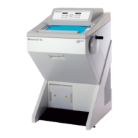
• To fix the complete unit, tighten the screws
(fig. 4.1) by using the attached tool.
• Install the separate packed handwheel
handle.
Warning:
Instead of the handwheel handle, a
transportation screw (fig. 4b.1) is
inserted into the handwheel. This way,
the handwheel is tightly and securely
connected with the housing of the cryostat. It
is absolutely necessary to remove this
transportation screw before the initial turn-
on!
• Loosen the transportation screw (fig. 4b.1)
via the Allan key, size 6.
• Now fix the separately packed handwheel
handle on the handwheel with the attached
screw by means of the Allan key.
Fig. 4
Fig. 4a
Fig. 4b
SW13
1
1
2
1