Deactivating swap...
Unmounting local filesystems...
[695413.959234] Power down.
[695413.989531] System Halted, OK to turn off power
Check Light Emitting Diode (LED) on the Avaya Virtual
Services Platform 4000
The figures and tables in the following sections describe the LEDs on the Avaya Virtual Services
Platform 4000 switches. The tables describe LED operation for a switch that finishes the power-on
self-test.
Front panel LEDs
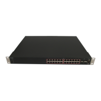
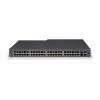
The following diagram illustrates the components on the front panels of the Avaya VSP 4000
4450GTX-HT-PWR+ switch.
For detailed explanations of the states indicated by each front panel LED type, see the following
sections:
• Switch LED state indicators on page 33
• Port LED state indicators on page 34
Figure 6: VSP 4450GTX-HT-PWR+
1. VSP 4000 USB port
2. Switch LEDs
3. 10/100/1000 Base TX RJ-45 ports with PoE+ (LEDs above ports)
4. 100/1000 Mbps SFP transciever modules
5. 1/10G SFP + ports
6. Console Port
Warning:
Fiber optic equipment can emit laser or infrared light that can injure your eyes. Never look into
an optical fiber or connector port. Always assume that fiber-optic cables are connected to a light
source. For a translation of this statement, see
Translations of safety messages on page 36.
Installing the Avaya VSP 4000 4450GTX-HT-PWR+
32 Installing the Avaya Virtual Services Platform 4000 VSP4450GTX-HT-PWR+ August 2014
Comments? infodev@avaya.com

 Loading...