2. Remove the camera stabilizing cartons before connecting the camera to avoid damage to
the system.
3. Insert the following connectors on the camera cable to the ports on the back of the camera,
as shown in
Figure 23: Connecting cables to the back of the camera on page 51:
• The DVI connector to the DVI socket
• The 8-pin connector to the IN (RS232C) socket
• The power connector to the DC IN 12V socket
Figure 23: Connecting cables to the back of the camera
4. With the camera turned off, set the System Select switch on back of the camera to 7 using a
slotted 2.5 mm screwdriver (Figure 23: Connecting cables to the back of the camera on
page 51).
This is only for Premium, Advanced, and Standard II cameras.
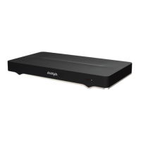
5. Insert the two connectors on the other end of the camera cable to the ports on the XT Codec
Unit (
Figure 24: Connecting the camera cables to the XT Codec Unit on page 52).
• Connect the HDMI plug to the vertical socket.
• Connect the other plug (power) to the horizontal socket.
We recommend keeping the DVI socket available for a computer connection (for example, to
share content in a videoconference).
Connecting Cameras or DVD players
January 2017 Avaya Scopia
®
XT Series Deployment Guide 51
Comments on this document? infodev@avaya.com
 Loading...
