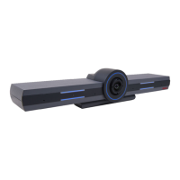
Figure 28: Connecting cables to the back of the camera
Note that this is an example diagram. The back panel for Deluxe and Flex cameras is
different from this one.
4. Attach the two connectors on the other end of the camera cable as shown in
Figure 29:
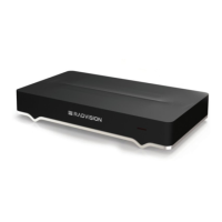
Connecting cables to the XT5000 Series on page 58 and Figure 30: Connecting cables to
the XT7000 Series on page 58:
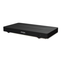
a. For the XT5000 Series: The HDMI connector to the HDMI socket labeled 1 on the
Avaya Scopia
®
XT Camera Switch.
b. For the XT7000 Series: The HDMI connector to the HDMI socket labeled 1 on the
XT7000 Series.
c.
The connector for power and serial control must be connected to the
horizontal
socket on the XT Codec Unit.
Connecting Cameras or DVD players
January 2017 Avaya Scopia
®
XT Series Deployment Guide 57
Comments on this document? infodev@avaya.com
 Loading...
