Chapter 3: USD Hardware and Software Overview 17
chapter 3
USD Hardware and Software Overview
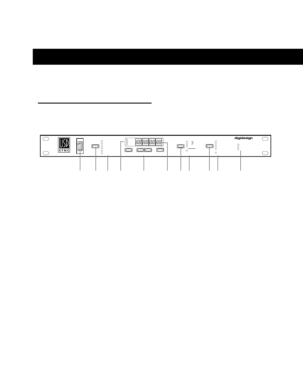
USD Front Panel
Controls and Displays
All USD local controls are on its front
panel; the rear panel is reserved for connec-
tors only. This section identifies each front
panel switch and display.
For information on rear panel connectors
and setup, see Chapter 2: Installing the USD.
1. AC Mains Power Switch
Down ( | ), USD power is on; Up ( O ), power
is off.
2. Clock Reference Switch
Selects the USD clock reference, with green
LEDs.
Clock References
VIDEO
LTC
DIGITAL
PILOT
BI PHASE/TACH
INTERNAL/VSO
3. Clock Reference LEDs
Green LEDs display the active clock refer-
ence, as selected with the Clock Reference
Switch.
Figure 1. USD Front Panel
CLOCK REFERENCE FRAME RATE
VIDEO
LTC
DIGITAL
PILOT
30
29.97
25
24
UNIVERSAL SLAVE DRIVER
LOCKED
SPEED CAL
REMOTE MODE
BI-PHASE/TACH
INTERNAL/VSO
44.1 kHz
48 kHz
PULL UP
PULL DOWN
DF
POSITIONAL REFERENCE
LTC
VITC
BI-PHASE
GENERATE
SET
DOWN
UP
RUN/STOP
CLEAR
1234 5 678 910 11