the mounting points on the junction box.
5. Usethestar-shapedscrewdrivertotightenthe4captivescrewsandsecurethecameratothejunctionbox.
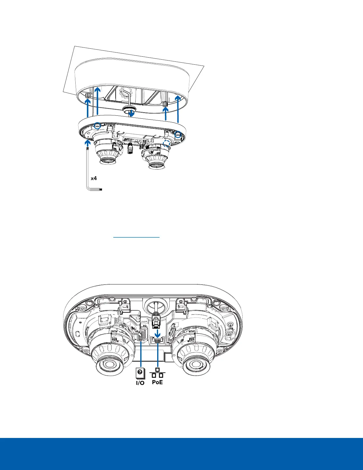
Connecting Cables
Refer to the diagrams in the Overview section for the location of the different connectors and status LEDs on
the camera base.
1. Connect a network cable to the camera's Ethernet port (RJ-45 connector).
Power the camera using the network cable with Power over Ethernet (PoE) IEEE 802.3af Class 3. The
status LEDs turn on when the camera receives power.
Connecting Cables 22
 Loading...