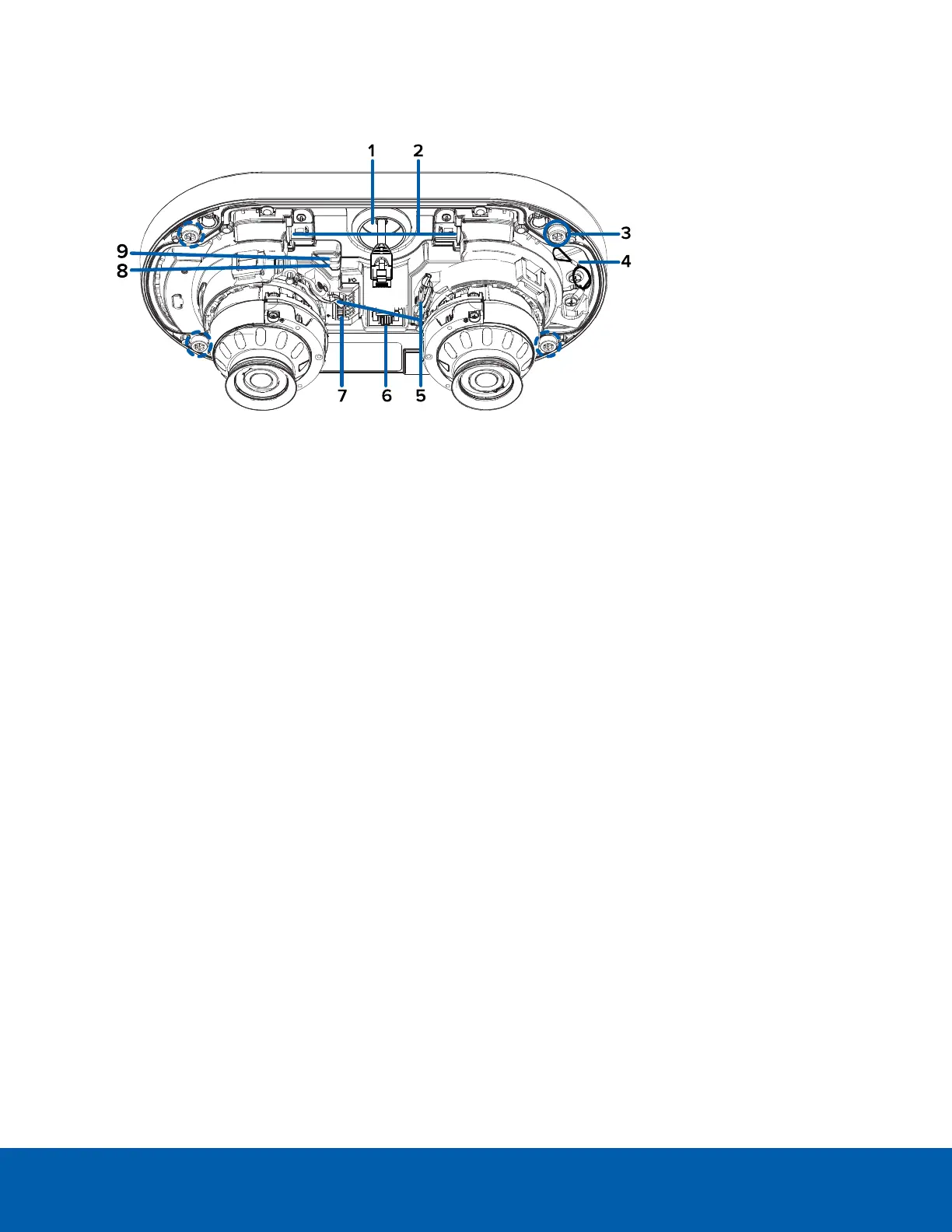
Internal View
1.
Cable entry hole
An entry hole for the cables required for camera operation.
2.
microSD card slots (x2)
Accepts up to two microSD cards for onboard storage. Install microSD cards so the metal contacts are
facing the base of the camera. For more information, see (Optional) Configuring Onboard Storage on
page37.
3.
Mounting screws
Screws for mounting the camera base to the mounting plate, junction box, or NPT adapter.
4.
Lanyard
Anchors the cover to the camera base.
5.
Pan and tilt locking latch (x2)
Locking mechanism to lock and unlock pan, tilt and azimuth adjustments for each camera head.
6.
Ethernet port
Accepts an Ethernet connection to a network. Server communication and image data transmission
occurs over this connection. Also receives power when it is connected to a network that provides
Power over Ethernet.
7.
I/O connector block
Provides connections to external input/output and audio devices.
If using the optional electrical box wall plate adapter or NPT adapter, align the mounting posts with the
mounting slots.
8.
Link LED indicator
Amber LED indicates if there is an active connection in the Ethernet port.
9.
Connection status LED indicator
Green LED provides information about device operation. For more information, see Connection Status
LED Indicator on page39.
Internal View 2
 Loading...