CANDPSX user manual rev 2 Page 40 of 42
____________________ _
Modbus (open)/Jbus (closed) selection
Reserved for future developments
Reserved for future developments
Tab. .7: Jumpers.
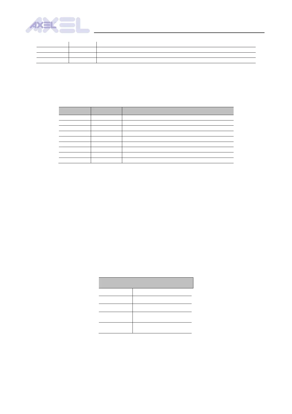
11.6 LEDS
The module mounts 9 LEDs for immediate dignostics (see § 38)
Status of main voltage supply (steady)
Status of CAN voltage supply (steady)
Status of Profibus voltage supply (steady)
Profibus data-exchange (steady while data exchanged)
Profibus driver errore (steady if error)
CAN driver error (see § 13)
Status of CAN driver (see § 13)
Status of RS232 Modbus communication (blinking)
Tab. .8: Meaning of LEDs
11.7 GUIDE TO HARDWARE INSTALLATION
Close the jumper TM-C1 if the board is the last element of a CAN bus network
Connect the signal SHIELD of the connector M1 to the nearest earth point
Connect the signals CAN_L and CAN_H of the connector M1
Connect the braiding of the CAN bus cable to earth
Connect the signal CAN_GND of the connector M1 of all the CAN modules, as the
CAN interface is not isolated. This guarantees that the voltage between tranceivers
never reaches the maximum level
Install the board in an omega guide
Supply the module with 18V – 36V DC through the connector M3
Mechanical characteristics