4-15
Assembly
Before assembly, check the parts for scratches, damage, deformation, peeling paint or any
other abnormalities. To assemble the actuator, proceed as follows:
A. Direct action models
• See Figure 4-8.
(1) Secure the diaphragm case (bottom) with the four bolts to the yoke. At the same time, set
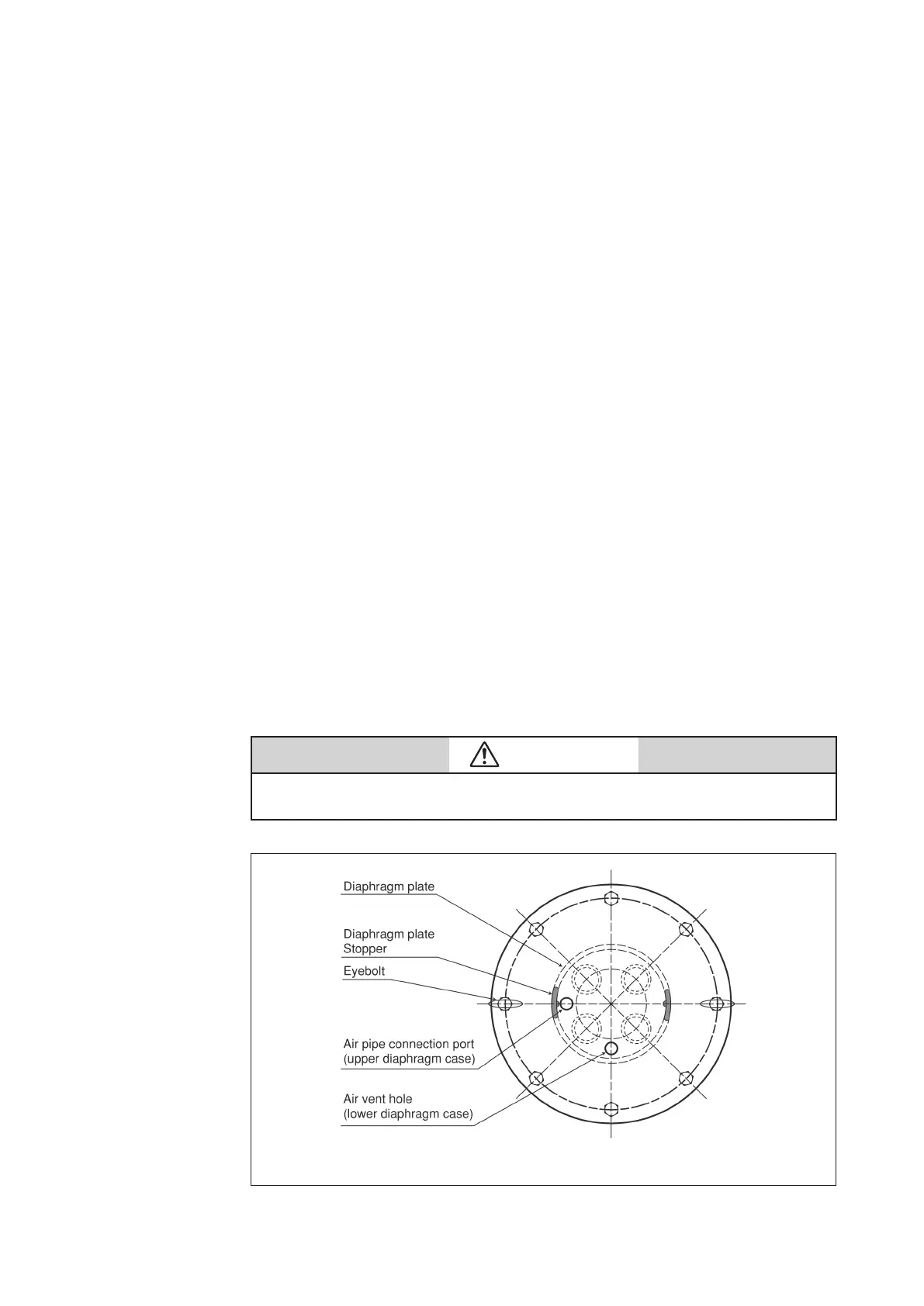
the air vent hole as in Figure 4-10. For model PSA1D actuator, secure the spring plate to
the diaphragm case and yoke.
(2) Fasten the spring place and install the springs onto the spring plate (see Figure 4-10).
(3) Insert the actuator rod (with diaphragm connected) into the bushing. Be careful to
prevent the bushing's inside surface or dust seal form being damaged by the threaded
section of the rod. If possible, cover the threaded section with adhesive tape.
(4) Rotate the actuator rod, locating the diaphragm plate stopper as shown in Figure 4-10.
(5) Place the top diaphragm case and secure it with the pair of eyebolts.
Note: Set the air pipe connection port to the location shown in Figure 4-10. Tighten
the pair of eyebolts uniformly and alternately. The initial setting of the springs is
completed by tightening these eyebolts.
(6) Clamp the diaphragm case with clamping bolts.
(7) Install the stem connector. Connect the air pipe to its connection port at the top
diaphragm case.
(8) After completing assembly, check the following:
• Apply air pressure of 500 kPa {5 kgf/cm
2
} through the air pipe connection port at the
top diaphragm case, and check the diaphragm periphery for air leakage with soapy
water.
• Check that the actuator operates smoothly through to its full stroke by operating it as an
independent unit.
CAUTION
Install packing for the rod and dustseal in the correct direction. Refer to Figure 4-8.
Figure 4-10 Direct Action Models Model PSA1D Actuator
 Loading...


