14
Chapter 3. Mounting and Wiring
z
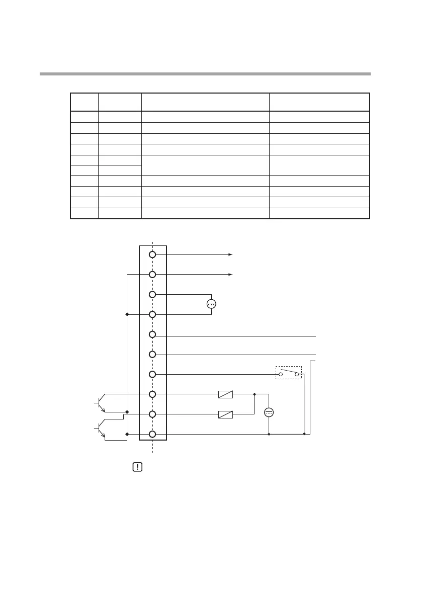
Connector signal names
Pin No. Signal Description Notes
1 DC OUT+ Instantaneous ow rate positive output
2 DC OUT- Instantaneous ow rate negative output
3 V+ Power + (12 to 24 V DC)
4 GND Power GND
5 DA For RS-485 communications Connect only when an RS-485
model is used.
6 DB
7 D IN Totalized ow count reset input
8 EV 2 Event output 2 / totalizer pulse output
9 EV 1 Event output 1 / serial data output
10
EV COM/SG Event output common / SG for RS-485
z
Wiring example
Handling Precautions
• Power source GND, instantaneous flow rate output (-), and
event output common lines are all connected inside this
device. If these lines are connected to an external device
through a common power supply, interference will cause
device failure or faulty operation.
• Take care that the event output does not exceed the output
rating of this device. Also, if driving a relay, use a relay with
a built-in diode for coil surge absorption. Failure to do so
might cause device failure.
1
2
3
4
5
6
7
8
9
10
EV 2 (Gray)
EV 1 (White)
EV COM/SG (Black)
DC OUT + (Brown)
DC OUT - (Red)
V + (Orange)
GND (Yellow)
DA (Pink)
DB (Blue)
D IN (Green)
12 to 24 V DC
Instantaneous ow rate output
Load
(30 V DC max., 50 mA max.)
Internal circuit External connection example
(30 V DC max., 50 mA max.)
30 V DC
or less
}
RS-485
communications