3-8
Chapter 3. MOUNTING AND WIRING
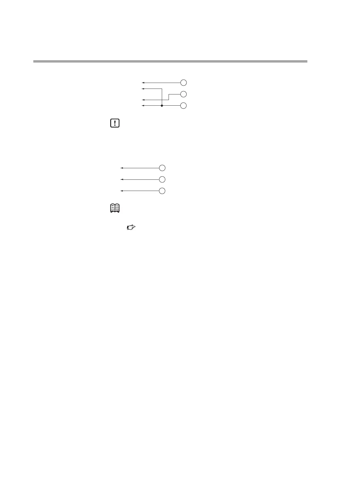
z Analog input/output (only for the model with analog I/O function)
7
8
Analog input
Analog output
SIGNAL GND
9
+
-
+
-
0 to 5 V or
1 to 5 V input
0 to 5 V or
1 to 5 V output
Handling Precautions
• Do not apply a negative voltage or a voltage exceeding 5 V to the analog
I/O terminals. Doing so might cause malfunction or equipment failure.
z RS-485 communication (only for the model with RS-485 communication function)
7
8
DA
DB
SIGNAL GND
9
DA
DB
SG
Note
• For details on how to connect the RS-485 communications,
Panel Mount Mass Flow Controller Model MPC9500/0002/0005/0020
User's Manual for Communication Functions CP-SP-1154E.