Wiring the Zeus Display | 33
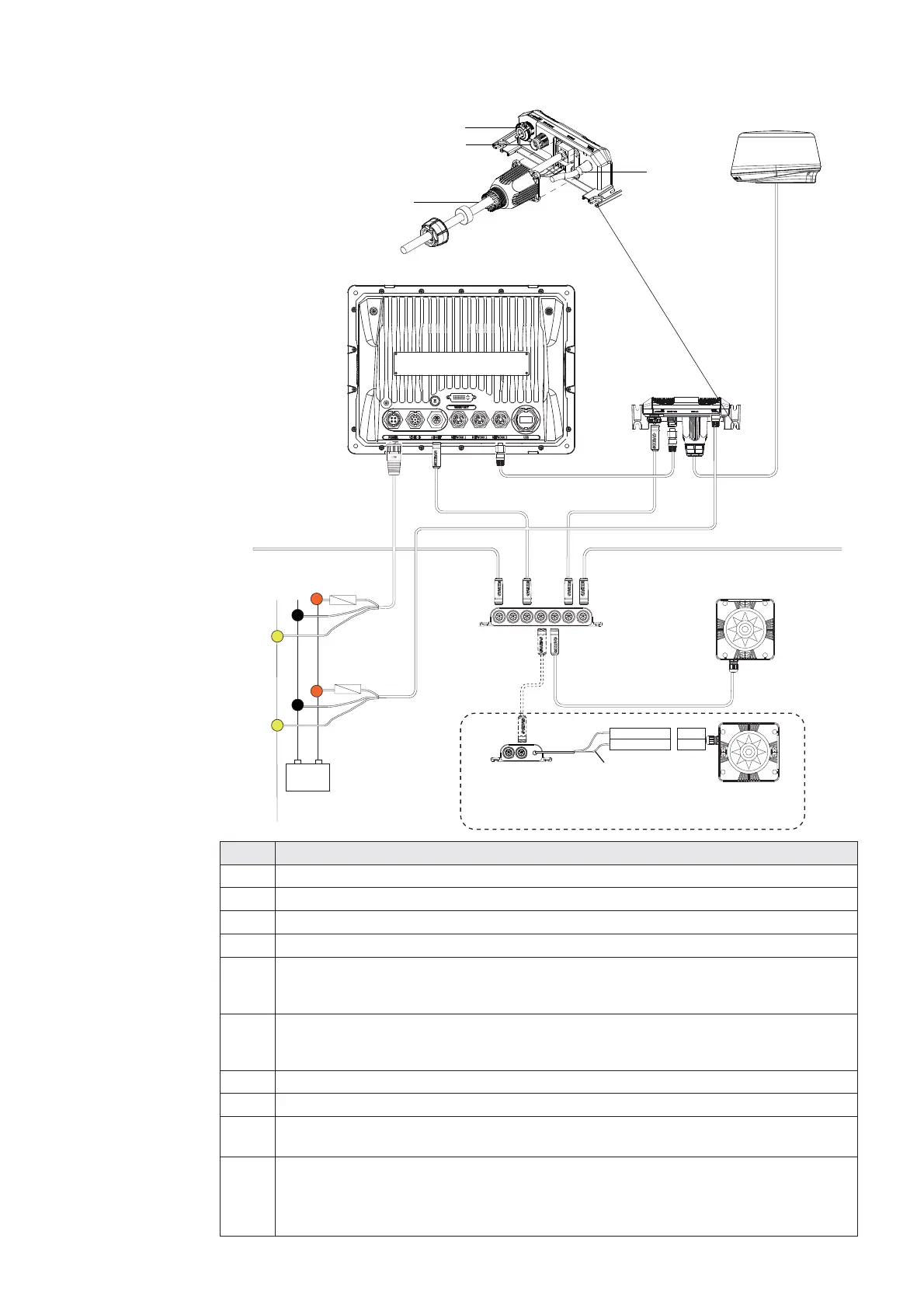
Connecting BroadBand™ Radar
+
_
B
C
D
E
FF
G
G
IJ
HH
A
Power
Scanner cable
SimNet
Network
Brown RX-
White RX+
AT10HD
NMEA0183 to SimNet
Converter Heading Only
Cut off 12 Pin
plug to expose bare wires
NMEA0183 10 Hz Heading
(e.g Gyro, Sat Compass)
Alternative: NMEA0183 heading
TX-
TX+
Key Description
AZeus Display.
B BroadBand™ Radar system for Zeus. Includes parts C,D and E.
C Scanner cable. 20 m (65 ft) : Optional 10 m (33 ft) and 30 m (98 ft).
D RI10 Radar interface box.
E Ethernet cable. BroadBand™ Radar comes with a 2 m (6.5 ft) 5 pin cable. The
RI10 can be connected directly to Zeus or via a Network Expansion Port. See
Ethernet cables yellow for more cable length options.
F SimNet Drop Cables: The BroadBand™ Radar and Zeus are connected to
the SimNet backbone BroadBand™ Radar uses heading at 10 hz to calculate
MARPA. (Not included)
G Power cable. (see Power section). Always use a fuse or breaker.
H SimNet backbone. Refer to SimNet section.
I Power control bus: In this case BroadBand™ Radar is connected to Power
Control Bus. BroadBand™ Radar is turned on when the Zeus is powered on.
J For MARPA and chart overlay use a heading sensor.
Either a SimNet / NMEA2000 heading sensor such as the GRC3. Or if a
NMEA0183 10 hz heading sensor is installed, convert to SimNet using a AT10HD
or connect to the NMEA in port on a Zeus. Refer NMEA0183 Wiring.
 Loading...