34 | Wiring the Zeus Display
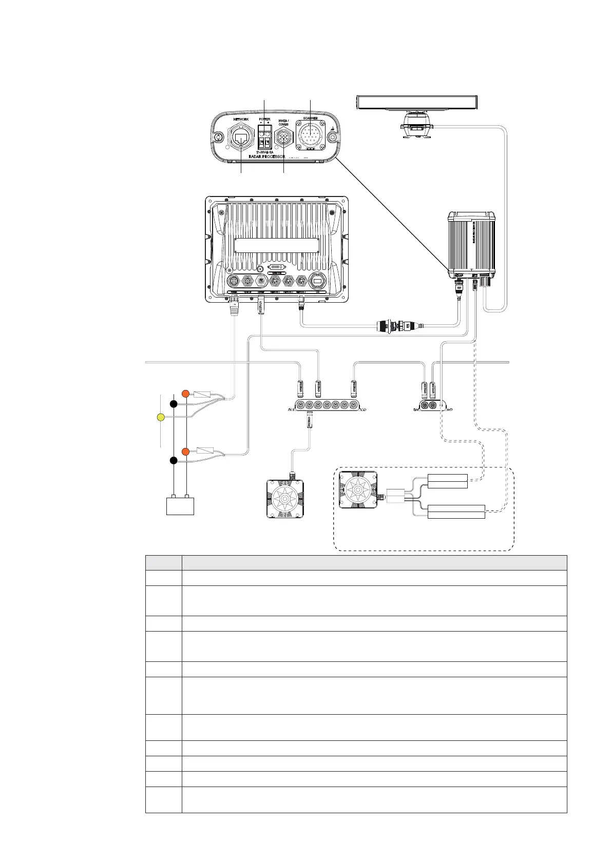
Connecting HD Radar
2 kW 12 V DC ONLY
4 kW & 6 kW 12 or 24 V DC
10 kW & 25 kW 24 V DC ONLY
+
_
B
C
D
D
E
F
K
K
G
I
J
HH
A
Ethernet
Scanner
AT10HD
NMEA0183 10 Hz Heading
(e.g Gyro, Sat Compass)
AA010070 Utility cable
AT10HD cable(cut off plug)
AA010070
Alternative: NMEA0183 heading
RX- White
RX+ Black/White
RX- Brown
RX+ White
TX-
TX+
Key Description
AZeus Display.
B HD radar system for Zeus. Includes parts C,D and E. 2kw & 4 kW Radome.
6 kW, 10 kw and 25 kW open array options
C Scanner cable. 20 m (65 ft) .
E Ethernet cable RJ45 (male/male). Available in 2,5 and 10 m, (6.5, 16.5 & 33 ft)
For cable options see Ethernet Cables RJ45.
D HD Radar Processor
F Ethernet Adapter cable. Yellow 5 pin (Male) to RJ45 (female) 2 m (6 ft). The HD
radar can be connected directly to Zeus or via a Network Expansion Port. See
Ethernet cables (yellow) for more cable length options.
G AT10HD: SimNet to NMEA0183 converter (Heading only @ 10 Hz). Provides
heading to the radar processor for MARPA calculations
H SimNet backbone. For more information refer to the SimNet section.
I SimNet drop cable.
J SimNet heading sensor
K Power cable. Make sure a fuse is used. See Radar installation manual for fuse
size. Note voltage requirements are model dependant
 Loading...