Hi Flow Sampler Introduction
Instruction 0055-9017
3
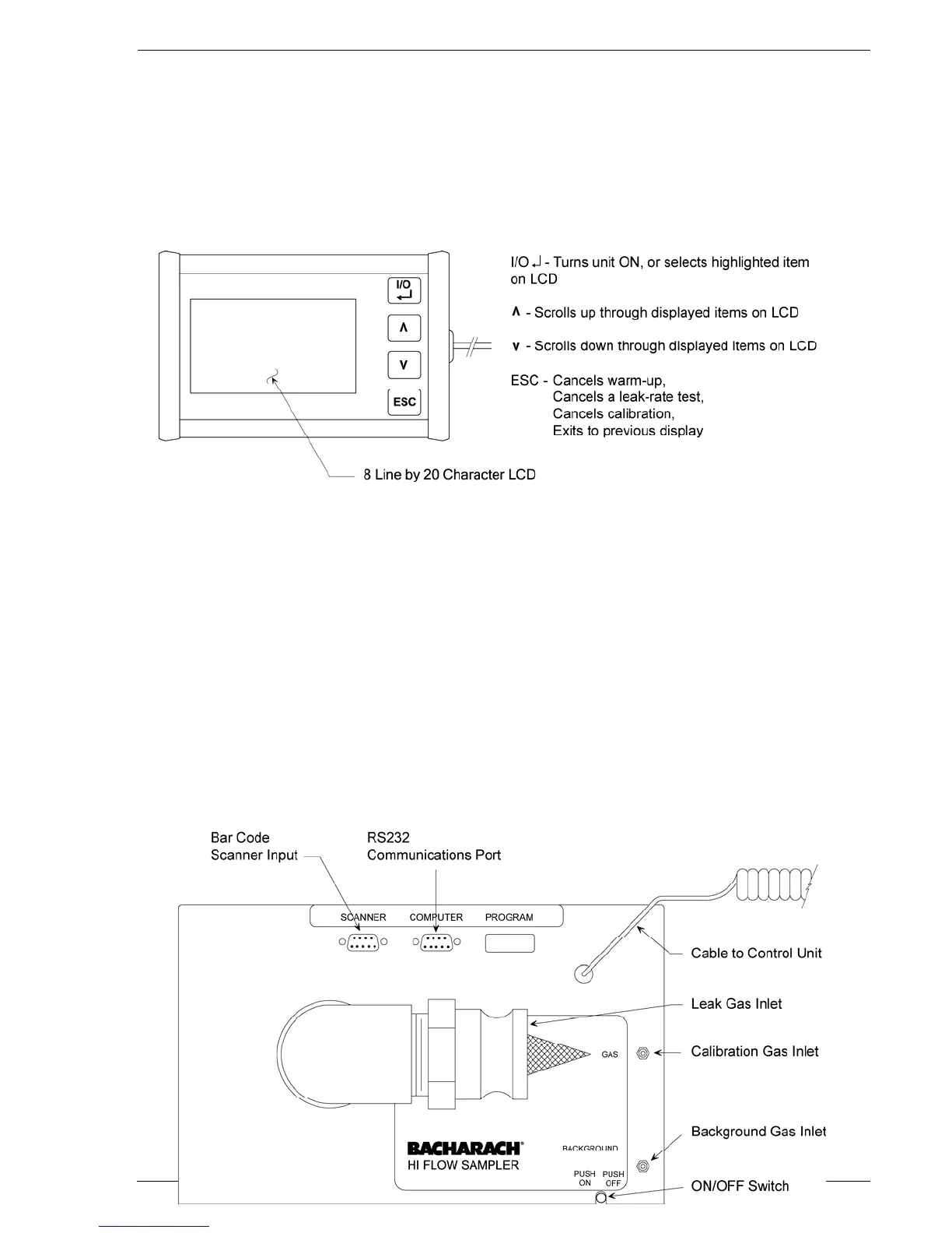
1.4 Control Unit Description
The control unit consists of an 8 line by 20 character LCD and the four
pushbuttons.
Figure 1-1. Control Unit
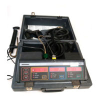
1.5 Top Panel Connections & Controls
The top panel contains the following items:
SCANNER – Bar code scanner input
COMPUTER – RS232 communications port for downloading stored
test data to an external computer
Leak Gas Inlet – Main hose connection used to collect gas from
leak source
BACKGROUND Gas Inlet – Gas hose connection used to sample
background levels of CH
4
GAS Inlet – Calibration gas connection
ON/OFF Switch – Turns unit ON and OFF
Figure 1-2. Top Panel Connections