Hi Flow Sampler Operation
Instruction 0055-9017
33
1 1 / 2 2 / 0 4 0 9 : 4 7 : 3 0
F l o w ( l p m ) 2 1 6 . 5
B a c k ( % ) 0 . 8 0
L e a k ( % ) 1 5 . 0 0
L e a k ( l p m ) 4 2 . 5
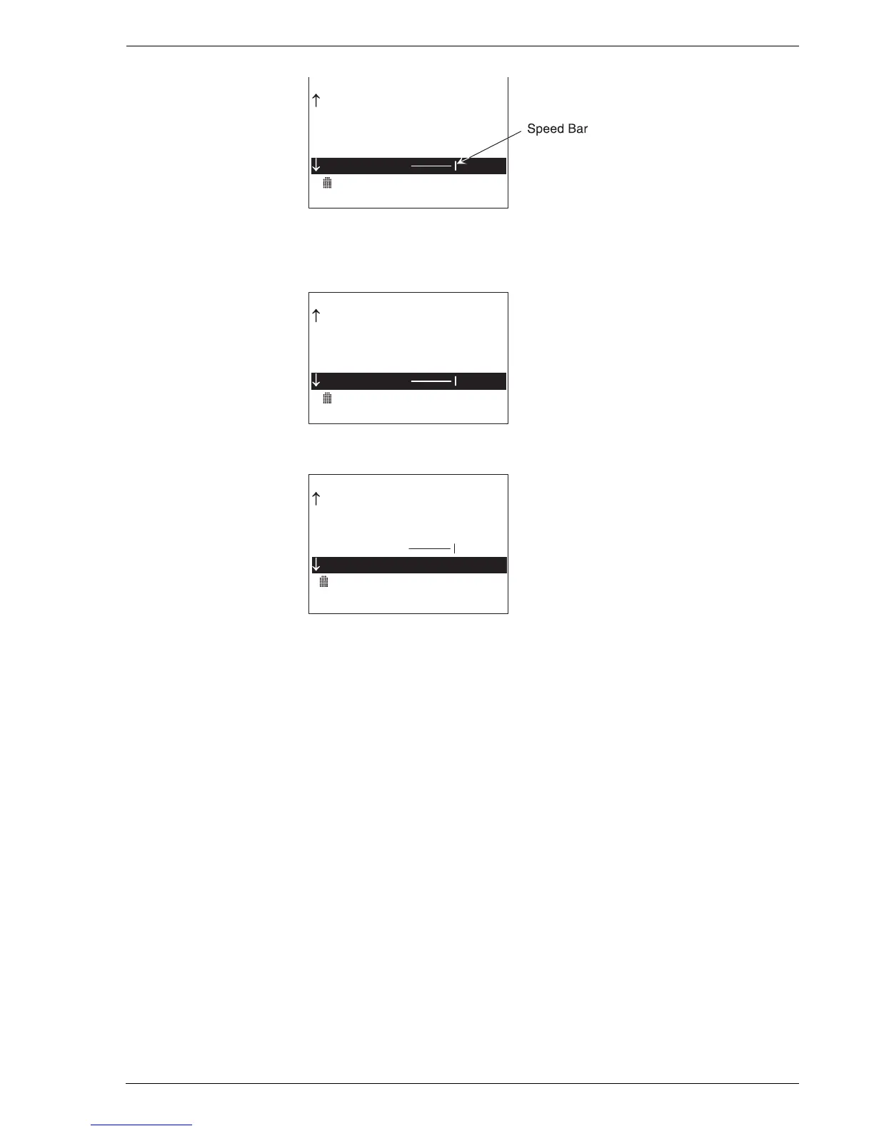
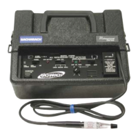
S p e e d ( L O < > H I )
[ 0 0 0 1 ] ( M ) - 1 -
S a m p l e T i m e - > 0 2 : 0 0
6. In the example below, the current flow rate is 216.5 lpm, the
background gas concentration is 0.8%, the leak concentration is 15%
gas, and the calculated leak rate is 42.5 lpm.
1 1 / 2 2 / 0 4 0 9 : 4 7 : 3 0
F l o w ( l p m ) 2 1 6 . 5
B a c k ( % ) 0 . 8 0
L e a k ( % ) 1 5 . 0 0
L e a k ( l p m ) 4 2 . 5
S p e e d ( L O < > H I )
[ 0 0 0 1 ] ( M ) - 1 -
S a m p l e T i m e - > 0 2 : 0 0
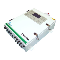
7. The measurement process continues until Stop is selected.
1 1 / 2 2 / 0 4 0 9 : 5 0 : 0 0
B a c k ( % ) 0 . 8 0
L e a k ( % ) 1 5 . 0 0
L e a k ( l p m ) 4 2 . 5
S p e e d ( L O < > H I )
S t o p
S a v e
S a m p l e T i m e - > 0 4 : 3 0
[ 0 0 0 1 ] ( M ) - 1 -
3.18.2 Leak Rate Measurement – Automatic 2-Stage Mode
Note: The Automatic 2-Stage Mode can only be selected if operating in the
Expanded Menu Mode. Refer to Section 3.8.
1. If not already done, place the instrument into its Automatic 2-Stage
measurement mode (denoted by the letter (A) appearing at the bottom
of the screen). Refer to Section 3.14.1 Automatic 2-Stage Measurement
Mode.
2. Choose an attachment that will ensure the complete capture of the
gas leak. Connect this attachment to the end of the Hi Flow
Sampler’s main sampling hose and position the attachment’s inlet
over the leak source.
3. Position the inlet of the instrument’s background gas sampling hose
opposite the leak source, such that the leak source will not
contribute to the background measurement.
4. Begin the measurement process by selecting Start from the Main
Screen.