PanaFlow™ XMT1000 User’s Manual 61
Chapter 3. Programming
3.7.4 Programming the Flow and Diagnostic Limits
Use steps as in “Log-in and Primary Pages” on page 30 to navigate to the Programming page. Refer to Figure 57 for
the Limit selection options.
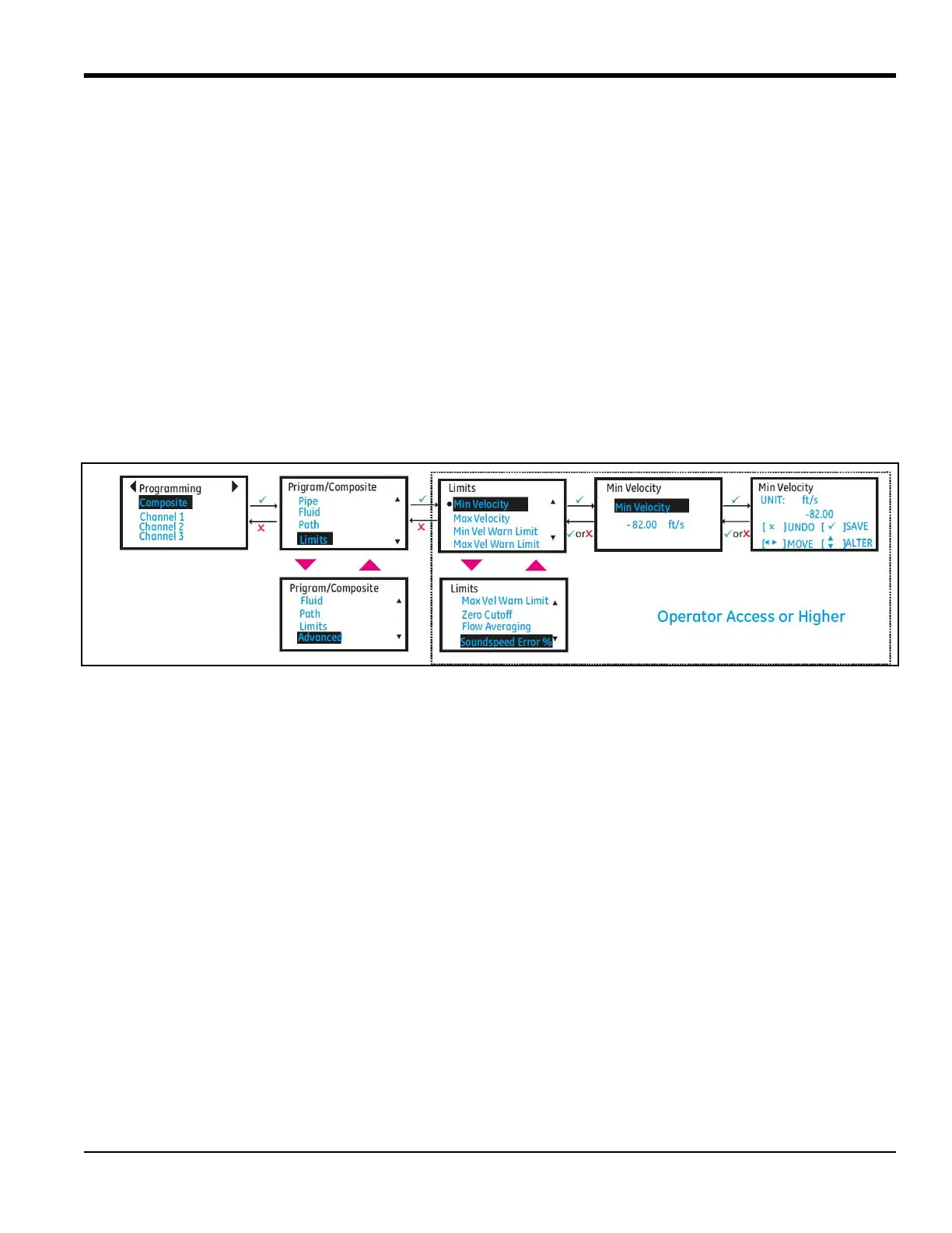
1. Select [Composite] and press [ENTER]. Scroll down and select [Limits] and press [ENTER].
2. Program the minimum flow velocity in [Min Velocity] and maximum flow velocity in [Max Velocity].
3. Program the appropriate velocity warning limits in [Min Vel Warn Limit] and [Max Vel Warn Limit]. The values
programmed in the warning limits should be tighter than those programmed in [Min Velocity] and [Max
Velocity] for early warning indications on the LCD and Errors.
4. To cutoff the near zero measurements program an appropriate value in [Zero Cutoff].
• In order to see stable averaged flow, program the time window for which flow should be averaged in [Flow
Averaging]. For example if a value 16 is programmed in for [Flow Averaging], the flow value will have the
average of the last 16s of flow values. This allows the flow values on the display and the outputs to be less
noisy.
5. If in section “Programming the Fluid” on page 59, Tracking was selected as OFF, program the [Soundspeed Error
%]. This configuration will be used to validate if the measured sound speed is within the programmed range of
the nominal sound speed. In case the measured sound speed is outside the [Soundspeed Error %] of the
nominal sound speed a E2: Soundspeed Error is reported.
Figure 57: Flow and Diagnostic Units
3.7.5 Programming Advanced Settings
Use steps as in “Log-in and Primary Pages” on page 30 to navigate to the Programming page. Refer to Figure 58 for
the Path configuration options.
1. Select [Composite] and press [ENTER]. Scroll down and select [Advanced] and press [ENTER].
2. Select [Inputs] and set the process [Fluid Temperature]. The Fluid temperature can be either fixed/static
(average process fluid temperature) or can be live values read from an Analog input or RTD (available as an
option).
3. Also set the [Ambient Temperature].
4. The [Transmit Voltage] should be set based on the viscosity of the process fluid and Pipe size. High viscous fluids
or large pipe sizes may need high voltage setting for signals to pass through.
5. Choose the [Refresh Rate] based on how fast you want the meter should make a measurement. The refresh rate
selection will not change the update rate on the Analog or Digital outputs. The Analog output and Digital outputs
are always updated at 4Hz.
6. This completes the basic programming options that may need to be updated based on flow application.
Advanced programming is already done at Baker Hughes Factory and during commissioning. Exit programming
by pressing [ESC] until Save options are displayed on the menu. Highlight [Save] or [Save & Logout] and Press
[ENTER] to save settings. The meter will not use the changed setting to make measurements until the settings
are explicitly saved.
 Loading...