www.bal dormotion.com
Basic Installation 3-7MN1901
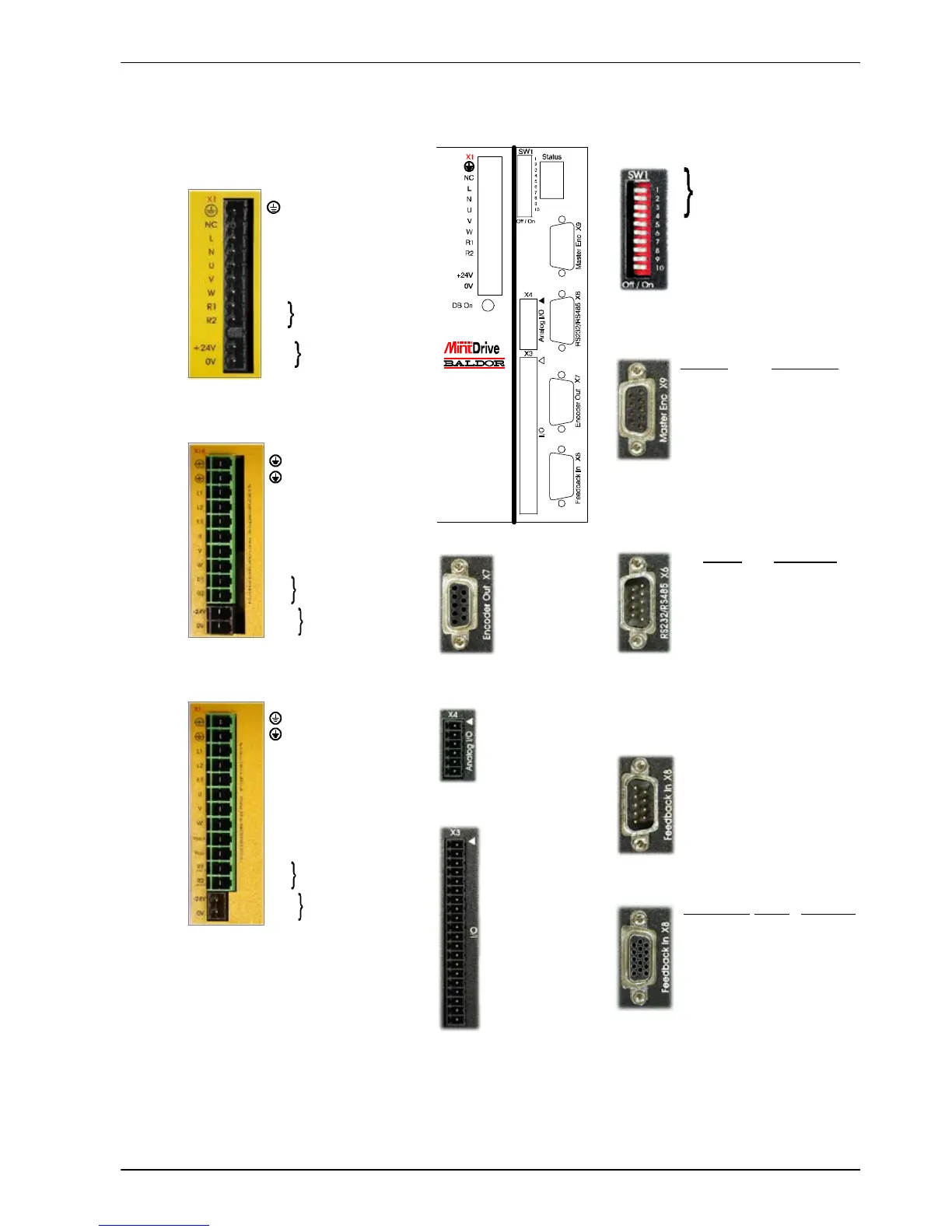
3.3 Connector locatio n s
Earth
NC (NC)
LACLine
N AC Neutral
UMotorU
VMotorV
WMotorW
R1 Regen Resistor
R2 (Dynamic Brake)
- (NC)
+24V Customer
0V suppli ed 24V
(MDHxxxxxx-xxx3
only)
Earth
Earth
L1 AC Phase 1
L2 AC Phase 2
L3 AC Phase 3
UMotorU
VMotorV
WMotorW
R1 Regen Resistor
R2 (Dynamic Brake)
+24V Customer supplied 24V
0V (MDH4xxxxx-xxx3 only)
1 AIN0+ (Demand+)
2 AIN0- (Demand-)
3AGND
4 Relay+ (DOUT3)
5 Relay-
6UserV+
7 CREF
8CGND
9 Drive Enable
10 DIN0
11 DIN1
12 DIN2
13 DIN3
14 DIN4 (Pulse)
15 DIN5 (Direction)
16 DIN6
17 DIN7
18 DOUT0
19 DOUT1
20 DOUT2
1 CHA+
2 CHB+
3 CHZ+
4 (NC)
5DGND
6 CHA-
7 CHB-
8 CHZ-
9 (NC)
RS232 RS485/422
1 (NC) (NC)
2RXD RX-
3TXD TX-
4 (NC) (NC)
5 0V GND 0V DGND
6 (NC) (NC)
7 RTS TX+
8CTS RX+
9 (NC - see section 4.4.3)
X3 General I/O
X6 RS232/RS485
X7 Encoder Out
X8 Feedback In
1REF+
2COS+
3SIN+
4 (NC)
5AGND
6REF-
7COS-
8SIN-
9 Chassis
Incremental EnDat Hi perface
1 CHA+ Data+ Data+
2 CHB+ Data- Data-
3 CHZ+ +5V +8V
4 Hall U+ +5V +8V
5 Hall U- DGND DGND
6 CHA- Shield Shiel d
7 CHB- Cos B- Cos B-
8 CHZ- (NC) (NC)
9 Hall W+ Clock- (NC)
10 Hall V+ Clock+ (NC)
11 +5V DGND DGND
12 (NC) Sin A- Sin A-
13 DGND Sin A+ Sin A+
14 Hall W- Cos B+ Cos B+
15 Hal l V- (NC) (NC)
Resolver option
Encoder options
X1 / X1A Power
Single-phase models
Three-phase models, 230-460V
Tightening torque for terminal block
connec tions is 0.5-0.6Nm (4.4-5.3 lb-in)
X9 Master Encoder
II
Options:
If there are other connectors on the front panel of your MintDriv e
II
, then an
option is fitted. See the other manual s supplied with your Mi ntDrive
II
.
* Warning! High voltages are present on
terminals label ed Vc c+ and Vcc -. Do not
make a connecti on to these terminals.
(NC) = Not Connec ted. Do not make a
connec tion to this pin.
Encoder Pulse & Dir.
1 CHA+ Pulse+
2 CHB+ Dir.+
3 CHZ+ (NC)
4 (NC) (NC)
5DGND (NC)
6 CHA- Pulse GND
7 CHB- Dir. GND
8 CHZ- (NC)
9+5V (NC)
1 Node
2 number
3 selection
4
5Hold
6 RS485 terminator
7 Offset tuning
8 Enable
9 (Reserved)
10 RS232/RS 485
SW1 DIP switches
1 Chassis
2AIN1+
3AIN1-
4AOUT0
5AOUT1
6AGND
X4 Analog I/O
Earth
Earth
L1 AC Phase 1
L2 AC Phase 2
L3 AC Phase 3
UMotorU
VMotorV
WMotorW
Vcc+ (NC)*
Vcc- (NC)*
R1 Regen Resistor
R2 (Dynamic Brake)
+24V Customer supplied 24V
0V (MDH2xxxxx-xxx3 only)
Three-phase models, 230V
 Loading...


