www.bal dormotion.com
Basic Installation 3-31MN1901
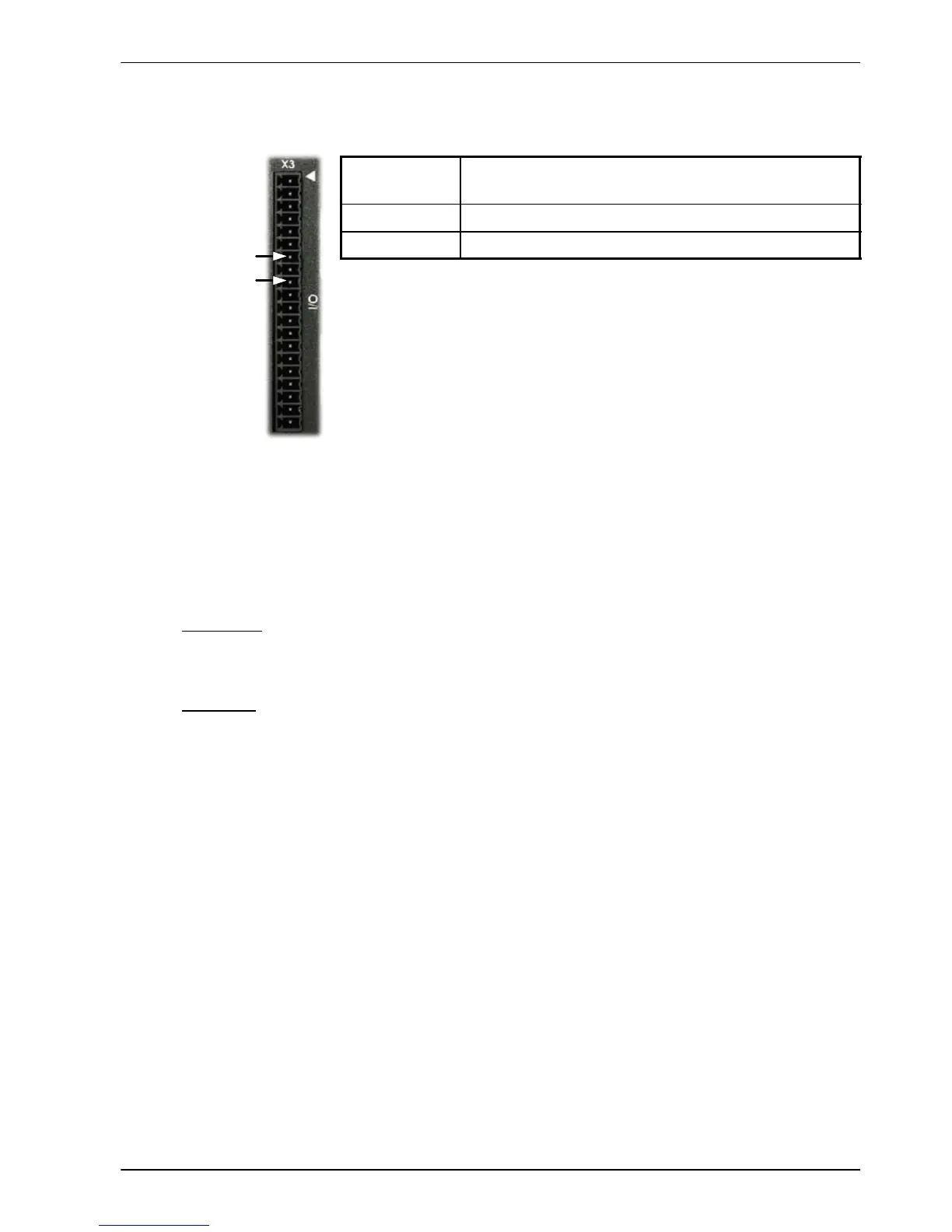
3.8 Drive enab le
Location Connector X3, pins 7 & 9 (Mating connector:
Phoenix MINI-COMBICON MC 1.5/20-ST-3,5)
Name Drive enable
Input voltage +24VDC (±20%)
To enable the MintDrive
II
and allow motion, three actions are necessary:
H A customer supplied externally generated 24VDC supply must be
connected between pins 7 and 9 of connector X3.
H The drive enable DIP switch (switch 8) must be in the On position.
H A drive enable command must be received.
These actions are explained in the following sections.
3.8.1 Drive enable - X3
The wiring to the drive enable input can be connected in one of two ways. Because CREF is
common to all the digital inputs, this has an effect on the sense of DIN0 to DIN7. Either
method provides a suitable drive enable input:
Active high
To cause the digital inputs to be active high (active when a voltage of +24VDC is applied to
them) connect +24VDC to pin 9 and 0V to pin 7 (CREF).
Active low
To cause the digital inputs to be active low (active when grounded) connect +24VDC to pin7
(CREF) and 0V to pin 9.
The drive enable connection can be wired directly or through an intermediate switch. If a
switch is used it should always be used to switch the signal to pin 9, with the signal to pin 7
(CREF) being hard-wired.
The sense of the digital inputs can also be configured in W orkBench v5 using the Digital inputs
tab of the Digital I/O tool. Alternatively, the Mint INPUTACTIVELEVEL keyword can be used to
select the sense of all the digital inputs (except drive enable). The state of the drive enable
input is displayed in the WorkBench v5 Spy window . It can also be checked (but not set) using
the Mint keyword DRIVEENABLESWITCH. See the Mint help file for details.
The drive enable input is rising edge triggered, but is only sampled every 1ms. For the drive to
become enabled, the input signal must have been inactive (off) for at least one sample, and
active (on) at the next sample. Care must be taken to avoid signal bounce on the drive enable
input, since any falling edge detected after the drive has become enabled will disable the drive
immediately . The drive cannot then be re-enabled until the input has been inactive (off) for at
least one sample, as described above.
ENABLE 9
CREF 7
 Loading...


