www.bal dormotion.com
3-26 Basic Installation MN1901
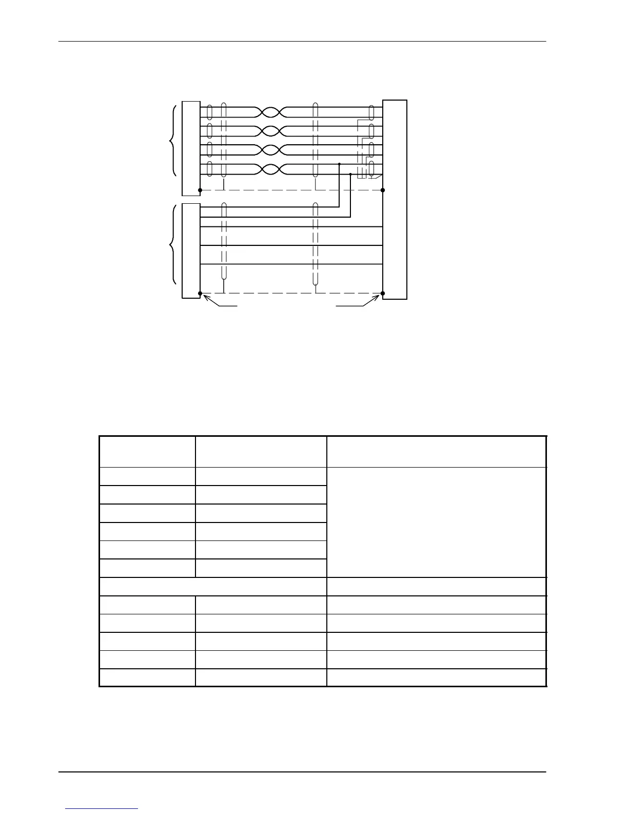
3.7.2.2 Encoder cable connections - linear motors
CHA+
CHA-
CHB+
CHB-
+5V
DGND
1
6
2
7
3
8
11
X8
Encoder
Feedback
CHZ+ (INDEX)
CHZ- (INDEX)
4
5
9
14
10
15
13
Hall U+
Hall U-
Hall W+
Hall W-
Hall V+
Hall V-
12 (NC)
Hall
Feedback
Connect overall shield to
connec tor backs hells.
Twisted pairs
Connect internal
shields to DGND.
Leave pins
5, 12, 14, 15
unconnec ted
Motor
Figure 15 - Encoder cable connections - linear motors
3.7.2.3 Encoder cable pin configuration - linear motors
Linear motors use two separate cables (encoder and Hall). The cores of these two cables
must be wired to the appropriate pins of the 15-pin D-type mating connector (supplied):
Signal name
MintDrive
II
X8 pin
Encoder cable internal wire colors
CHA+ 1
CHA- 6
CHB+ 2
Please refer to MN1800 Linear Motors
CHB- 7
 Loading...


