www.bal dormotion.com
6-4 Preset Moves & PLC Task MN1901
6.2.3.1 Configuring digital inputs to control presets
The default combination of digital inputs used for triggering presets is 6, 7, 0 and 1 to select
the preset, and 5 to trigger the preset. However, this combination can be changed to use any
four (or fewer) contiguous inputs, plus a trigger input. The inputs form a bit pattern that
represents the preset to be selected. Consequently, if the application requires only a small
number of different preset moves, you can reduce the number of inputs required to select the
preset.
The following table shows the combinations of digital inputs that must be active to trigger each
preset index move. The table shows 4 inputs being used (0 - 3), allowing 16 presets to be
selected:
Preset index
(Bit pattern
sum)
Digital input 0
(Bit pattern
value: 1)
Digital input 1
(Bit pattern
value: 2)
Digital input 2
(Bit pattern
value: 4)
Digital input 3
(Bit pattern
value: 8)
0 0 0 0 0
1 1 0 0 0
2 0 1 0 0
3 1 1 0 0
4 0 0 1 0
5 1 0 1 0
6 0 1 1 0
7 1 1 1 0
8 0 0 0 1
9 1 0 0 1
10 0 1 0 1
11 1 1 0 1
12 0 0 1 1
13 1 0 1 1
14 0 1 1 1
15 1 1 1 1
Table 3 - Preset selection using digita l input s 0-3
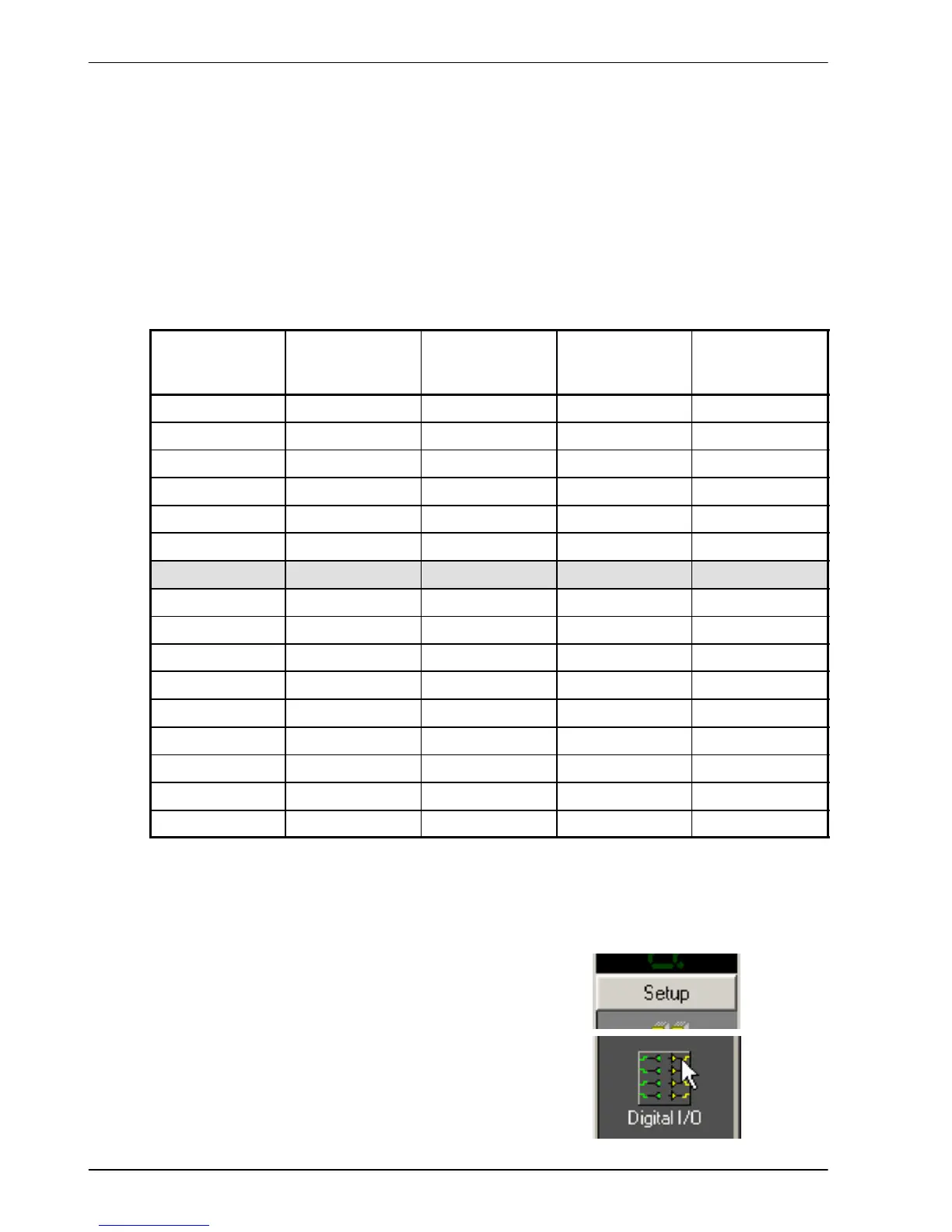
For example, to select preset move 6, digital inputs 1 and 2 must be active. The choice of
digital inputs is configured using the Digital I/O tool:
1. In the Toolbox, click Setup then click the
Digital I/O icon.
 Loading...


